

Rolls-Royce Merlin
Aircraft engine family
- 36 min read
- 7 chapters

Related on Lably
Through Kilometres per hour
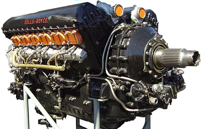
Initially known as the PV-12, it was dubbed Merlin after the company convention of naming its four-stroke piston aero engines for birds of prey. The engine benefitted from the racing experiences of precursor engines in the 1930s. After several modifications, the first production variants of the PV-12 were completed in 1936. The first operational aircraft to enter service using the Merlin were the Fairey Battle, Hurricane, and Spitfire. Experience in use led to a series of rapidly applied developments that markedly improved the engine's performance and durability. Starting at 1,000 horsepower (750 kW) for the first production models, most late-war versions produced just under 1,800 horsepower (1,300 kW). The final version, used in the de Havilland Hornet, had over 2,000 horsepower (1,500 kW).
Some 50 versions of the Merlin were built by Rolls-Royce in Derby, Crewe, and Glasgow, as well as by Ford of Britain at their Trafford Park factory near Manchester. The Packard V-1650 was a version of the Merlin built in the United States. A de-rated version was the basis of the Rolls-Royce/Rover Meteor tank engine. After the war, the Merlin was largely superseded by the Rolls-Royce Griffon for military use, although new variants were designed and built for airliners and military transport aircraft. Production ceased in 1950 after a total of almost 150,000 engines had been delivered.
Merlin engines remain in Royal Air Force service today with the Battle of Britain Memorial Flight, and power many restored aircraft in private ownership worldwide.
Design and development
Origin
In the early 1930s, Rolls-Royce started planning its future aero-engine development programme and realised there was a need for an engine larger than their 21-litre (1,296 cu in) Kestrel, which was being used with great success in a number of 1930s aircraft. Consequently, work was started on a new 1,100 hp (820 kW)-class design known as the PV-12, with PV standing for Private Venture, 12-cylinder, as the company received no government funding for work on the project. The PV-12 was first run on 15 October 1933 and first flew in a Hawker Hart biplane (serial number K3036) on 21 February 1935. The engine was originally designed to use the evaporative cooling system then in vogue. This proved unreliable and when ethylene glycol from the U.S. became available, the engine was adapted to use a conventional liquid-cooling system. The Hart, as a Merlin testbed, completed over 100 hours of flying with the Merlin C and E engines.
In 1935, the Air Ministry issued a specification, F10/35, for new fighter aircraft with a minimum airspeed of 310 mph (500 km/h). Fortunately, two designs had been developed: the Supermarine Spitfire and the Hawker Hurricane; the latter designed in response to another specification, F36/34. Both were designed around the PV-12 instead of the Kestrel, and were the only contemporary British fighters to have been so developed. Production contracts for both aircraft were placed in 1936, and development of the PV-12 was given top priority as well as government funding. Following the company convention of naming its piston aero engines after birds of prey, Rolls-Royce named the engine the Merlin after a small, Northern Hemisphere falcon (Falco columbarius).
Two more Rolls-Royce engines developed just prior to the war were added to the company's range. The 885 hp (660 kW) Rolls-Royce Peregrine was an updated, supercharged development of their V12 Kestrel design, while the 1,700 hp (1,300 kW) 42-litre (2,560 cu in) Rolls-Royce Vulture used four Kestrel-sized cylinder blocks fitted to a single crankcase and driving a common crankshaft, forming an X-24 layout. This was to be used in larger aircraft such as the Avro Manchester.
Although the Peregrine appeared to be a satisfactory design, it was never allowed to mature since Rolls-Royce's priority was refining the Merlin. As a result, the Peregrine saw use in only two aircraft: the Westland Whirlwind fighter and one of the Gloster F.9/37 prototypes. The Vulture was fitted to the Avro Manchester bomber, but proved unreliable in service and the planned fighter using it – the Hawker Tornado – was cancelled as a result. With the Merlin itself soon pushing into the 1,500 hp (1,100 kW) range, the Peregrine and Vulture were both cancelled in 1943, and by mid-1943 the Merlin was supplemented in service by the larger Griffon. The Griffon incorporated several design improvements and ultimately superseded the Merlin.
Development
Initially the new engine was plagued with problems such as failure of the accessory gear trains and coolant jackets. Several different construction methods were tried before the basic design of the Merlin was set. Early production Merlins were unreliable: common problems were cylinder head cracking, coolant leaks, and excessive wear to the camshafts and crankshaft main bearings.
Early engines
The prototype, developmental, and early production engine types were the:
- PV-12
- The initial design using an evaporative cooling system. Two built, passed bench type testing in July 1934, generating 740 hp (550 kW) at 12,000-foot (3,700 m) equivalent. First flown 21 February 1935.
- Merlin B
- Two built, ethylene glycol liquid cooling system introduced. "Ramp" cylinder heads (inlet valves were at a 45-degree angle to the cylinder). Passed Type Testing February 1935, generating 950 hp (710 kW) at 11,000-foot (3,400 m) equivalent.
- Merlin C
- Development of Merlin B; crankcase and cylinder blocks became three separate castings with bolt-on cylinder heads. First flight in Hawker Horsley 21 December 1935, 950 hp (710 kW) at 11,000-foot (3,400 m).
- Merlin E
- Similar to C with minor design changes. Passed 50-hour civil test in December 1935 generating a constant 955 hp (712 kW) and a maximum rating of 1,045 hp (779 kW). Failed military 100-hour test in March 1936. Powered the Supermarine Spitfire prototype.
- Merlin F (Merlin I)
- Similar to C and E. First flight in Horsley 16 July 1936. This became the first production engine, and was designated as the Merlin I. The Merlin continued with the "ramp" head, but this was not a success and only 172 were made. The Fairey Battle I was the first production aircraft to be powered by the Merlin I and first flew on 10 March 1936.
- Merlin G (Merlin II)
- Replaced "ramp" cylinder heads with parallel pattern heads (valve stems parallel to the cylinder bore axis) scaled up from the Kestrel engine. 400-hour flight endurance tests carried out at RAE July 1937; acceptance test 22 September 1937. It was first widely delivered as the 1,030 hp (770 kW) Merlin II in 1938, and production was quickly stepped up for Fairey Battle II.
- Merlin III
- Merlin II with standardised de Havilland/Rotol SBAC propeller shaft, and dual accessory-drive. 1,030 hp (770 kW) at 3,000 rpm at 10,250 feet (3,120 m) at +6.5 psi (45 kPa) boost. Formed basis for the Rolls-Royce/Rover Meteor tank engine
- "Racing" Merlin
- Racing engine for 1937/38 "Speed Spitfire" world speed record attempt. Merlin III with strengthened pistons, connecting rods, and gudgeon-pins, running on increased octane fuel, developed 2,160 hp (1,610 kW) at 3,200 rpm and +27 psi (190 kPa) boost, a power/weight ratio of 0.621 pounds per horsepower (0.378 kilograms per kilowatt). Completed 15-hour endurance run at 1,800 hp (1,300 kW), 3,200 rpm at +22 psi (150 kPa) boost.
- Merlin IV
- Merlin with pressure-water cooling for Armstrong Whitworth Whitley IV.
- Merlin V
- Merlin for Fairey Battle V.
- Merlin VIII
- Medium-supercharged Merlin developed for Fairey Fulmar I, rated 1,010 hp (750 kW) at 2,850 rpm at 6,750 feet (2,060 m), 1,080 hp (810 kW) at 3,000 rpm for take-off using 100-octane fuel.
- Merlin X
- First Merlin with two-speed supercharger, 1,145 hp (854 kW) in low gear at 5,250 feet (1,600 m), 1,010 hp (750 kW) in high gear at 17,750 feet (5,410 m). First of Rolls-Royce unitised "Power Plant" installation designs for this engine in 1937 and used in Handley Page Halifax I, Vickers Wellington II, and Armstrong Whitworth Whitley V and VII.
- Merlin XII
- Merlin fitted with 0.477:1 reduction gear installed in some Spitfire IIs with three-bladed Rotol constant-speed propeller. Rated at 1,150 hp (860 kW) at 3,000 rpm at 14,000 feet (4,300 m).
- Merlin XX
- Merlin X with Stanley Hooker re-designed supercharger incorporating re-designed inlet and improved guide vanes on impeller with revised blower gear ratios; 8:15:1 for low gear, 9:49:1 for high gear. New larger SU twin choke updraught carburettor. Engine interchangeable with Merlin X. Rated at 1,240 hp (920 kW) at 2,850 rpm in low gear at 10,000 feet (3,000 m) and +9 psi (62 kPa) boost; 1,175 hp (876 kW) at 2,850 rpm in high gear at 17,500 feet (5,300 m) at +9 lb boost. Revised Rolls-Royce unitised "Power Plant" installation design. Engine used in Bristol Beaufighter II, Boulton Paul Defiant II, Handley Page Halifax II and V, Hawker Hurricane II and IV, and Avro Lancaster I and III. First Merlin produced by Packard Motor Car Company as V-1650-1 and designated by Rolls-Royce as Merlin 28.
Production engines
The Merlin II and III series were the first main production versions of the engine. The Merlin III was the first version to incorporate a "universal" propeller shaft, allowing either de Havilland or Rotol manufactured propellers to be used.
The first major version to incorporate changes brought about through experience in operational service was the XX, which was designed to run on 100-octane fuel. This fuel allowed higher manifold pressures, which were achieved by increasing the boost from the centrifugal supercharger. The Merlin XX also utilised the two-speed superchargers designed by Rolls-Royce, resulting in increased power at higher altitudes than previous versions. Another improvement, introduced with the Merlin X, was the use of a 70%–30% water-glycol coolant mix rather than the 100% glycol of the earlier versions. This substantially improved engine life and reliability, removed the fire hazard of the flammable ethylene glycol, and reduced the oil leaks that had been a problem with the early Merlin I, II and III series.
The process of improvement continued, with later versions running on higher octane ratings, delivering more power. Fundamental design changes were also made to all key components, again increasing the engine's life and reliability. By the end of the war the "little" engine was delivering over 1,600 hp (1,200 kW) in common versions, and as much as 2,030 hp (1,510 kW) in the Merlin 130/131 versions specifically designed for the de Havilland Hornet. Ultimately, during tests conducted by Rolls-Royce at Derby, an RM17SM (an improved version of the RM14SM 'low altitude' Merlin 100-Series with larger diameter supercharger rotors and different valve timing) achieved 2,640 hp (1,970 kW) at 36 lb boost (103"Hg) on 150-octane fuel with water injection.
With the end of the war, work on improving Merlin power output was halted and the development effort was concentrated on civil derivatives of the Merlin. Development of what became the "Transport Merlin" (TML) commenced with the Merlin 102 (the first Merlin to complete the new civil type-test requirements) and was aimed at improving reliability and service overhaul periods for airline operators using airliner and transport aircraft such as the Avro Lancastrian, Avro York (Merlin 500-series), Avro Tudor II and IV (Merlin 621), Tudor IVB and V (Merlin 623), TCA Canadair North Star (Merlin 724) and BOAC Argonaut (Merlin 724-IC). By 1951 the time between overhauls (TBO) was typically 650–800 hours depending on use. By then single-stage engines had accumulated 2,615,000 engine hours in civil operation, and two-stage engines 1,169,000.
In addition, an exhaust system to reduce noise levels to below those from ejector exhausts was devised for the North Star/Argonaut. This "cross-over" system took the exhaust flow from the inboard bank of cylinders up-and-over the engine before discharging the exhaust stream on the outboard side of the UPP nacelle. As a result, sound levels were reduced by between 5 and 8 decibels. The modified exhaust also conferred an increase in horsepower over the unmodified system of 38 hp (28 kW), resulting in a 5 knot improvement in true air speed. Still-air range of the aircraft was also improved by around 4 per cent. The modified engine was designated the "TMO" and the modified exhaust system was supplied as kit that could be installed on existing engines either by the operator or by Rolls-Royce.
Power ratings for the civil Merlin 600, 620, and 621-series was 1,160 hp (870 kW) continuous cruising at 23,500 feet (7,200 m), and 1,725 hp (1,286 kW) for take-off. Merlins 622–626 were rated at 1,420 hp (1,060 kW) continuous cruising at 18,700 feet (5,700 m), and 1,760 hp (1,310 kW) for take-off. Engines were available with single-stage, two-speed supercharging (500-series), two-stage, two-speed supercharging (600-series), and with full intercooling, or with half intercooling/charge heating, charge heating being employed for cold area use such as in Canada. Civil Merlin engines in airline service flew 7,818,000 air miles in 1946, 17,455,000 in 1947, and 24,850,000 miles in 1948.
Basic component overview (Merlin 61)
From Jane's:
- Cylinders
- Twelve cylinders consisting of high-carbon steel liners set in two, two-piece cylinder blocks of cast "R.R.50" aluminium alloy having separate heads and skirts. Wet liners, i.e. coolant in direct contact with external face of liners. Cylinder heads fitted with cast-iron inlet valve guides, phosphor bronze exhaust valve guides, and renewable "Silchrome" steel-alloy valve seats. Two diametrically opposed spark plugs protrude into each combustion chamber.
- Pistons
- Machined from "R.R.59" alloy forgings. Fully floating hollow gudgeon pins of hardened nickel-chrome steel. Three compression and one oil-control ring above the gudgeon pin, and one oil-control ring below.
- Connecting rods
- H-section machined nickel-steel forgings, each pair consisting of a plain and a forked rod. The forked rod carries a nickel-steel bearing block which accommodates steel-backed lead-bronze-alloy bearing shells. The "small-end" of each rod houses a floating phosphor bronze bushing.
- Crankshaft
- One-piece, machined from a nitrogen-hardened nickel-chrome molybdenum steel forging. Statically and dynamically balanced. Seven main bearings and six throws.
- Crankcase
- Two aluminium-alloy castings joined on the horizontal centreline. The upper portion bears the wheelcase, supercharger and accessories; and carries the cylinder blocks, crankshaft main bearings (split mild-steel shells lined with lead bronze alloy), and part of the housing for the airscrew reduction gear. The lower half forms an oil sump and carries the oil pumps and filters.
- Wheelcase
- Aluminium casting fitted to rear of crankcase. Houses drives to the camshafts, magnetos, coolant and oil pumps, supercharger, hand and electric starters, and the electric generator.
- Valve gear
- Two inlet and two exhaust poppet valves of "K.E.965" steel per cylinder. Both the inlet and exhaust valves have hardened "stellited" ends; while the exhaust valves also have sodium-cooled stems, and heads protected with a "Brightray" (nickel-chromium) coating. Each valve is kept closed by a pair of concentric coil-springs. A single, seven-bearing camshaft, located on the top of each cylinder head operates 24 individual steel rockers; 12 pivoting from a rocker shaft on the inner, intake side of the head to actuate the exhaust valves, the others pivoting from a shaft on the exhaust side of the head to actuate the inlet valves.
Technical improvements
Most of the Merlin's technical improvements resulted from more efficient superchargers, designed by Stanley Hooker, and the introduction of aviation fuel with increased octane ratings. Numerous detail changes were made internally and externally to the engine to withstand increased power ratings and to incorporate advances in engineering practices.
Ejector exhausts
The Merlin consumed an enormous volume of air at full power (equivalent to the volume of a single-decker bus per minute), and with the exhaust gases exiting at 1,300 mph (2,100 km/h) it was realised that useful thrust could be gained simply by angling the gases backwards instead of venting sideways.
During tests, 70 pounds-force (310 N; 32 kgf) thrust at 300 mph (480 km/h), or roughly 70 hp (52 kW) was obtained, which increased the level maximum speed of the Spitfire by 10 mph (16 km/h) to 360 mph (580 km/h). The first versions of the ejector exhausts featured round outlets, while subsequent versions of the system used "fishtail" style outlets, which marginally increased thrust and reduced exhaust glare for night flying.
In September 1937 the Spitfire prototype, K5054, was fitted with ejector type exhausts. Later marks of the Spitfire used a variation of this exhaust system fitted with forward-facing intake ducts to distribute hot air out to the wing-mounted guns to prevent freezing and stoppages at high altitudes, replacing an earlier system that used heated air from the engine coolant radiator. The latter system had become ineffective due to improvements to the Merlin itself which allowed higher operating altitudes where air temperatures are lower. Ejector exhausts were also fitted to other Merlin-powered aircraft.
Supercharger
Central to the success of the Merlin was the supercharger. A.C. Lovesey, an engineer who was a key figure in the design of the Merlin, delivered a lecture on the development of the Merlin in 1946; in this extract he explained the importance of the supercharger:
The impression still prevails that the static capacity known as the swept volume is the basis of comparison of the possible power output for different types of engine, but this is not the case because the output of the engine depends solely on the mass of air it can be made to consume efficiently, and in this respect the supercharger plays the most important role ... the engine has to be capable of dealing with the greater mass flows with respect to cooling, freedom from detonation and capable of withstanding high gas and inertia loads ... During the course of research and development on superchargers it became apparent to us that any further increase in the altitude performance of the Merlin engine necessitated the employment of a two-stage supercharger.
As the Merlin evolved so too did the supercharger; the latter fitting into three broad categories:
- Single-stage, single-speed gearbox: Merlin I to III, XII, 30, 40, and 50 series (1937–1942).
- Single-stage, two-speed gearbox: experimental Merlin X (1938), production Merlin XX (1940–1945).
- Two-stage, two-speed gearbox with intercooler: mainly Merlin 60, 70, and 80 series (1942–1946).
The Merlin supercharger was originally designed to allow the engine to generate maximum power at an altitude of about 16,000 ft (4,900 m). In 1938 Stanley Hooker, an Oxford graduate in applied mathematics, explained "... I soon became very familiar with the construction of the Merlin supercharger and carburettor ... Since the supercharger was at the rear of the engine it had come in for pretty severe design treatment, and the air intake duct to the impeller looked very squashed ..." Tests conducted by Hooker showed the original intake design was inefficient, limiting the performance of the supercharger. Hooker subsequently designed a new air intake duct with improved flow characteristics, which increased maximum power at a higher altitude of over 19,000 ft (5,800 m); and also improved the design of both the impeller and the diffuser which controlled the airflow to it. These modifications led to the development of the single-stage Merlin XX and 45 series.
A significant advance in supercharger design was the incorporation in 1938 of a two-speed drive (designed by the French company Farman) to the impeller of the Merlin X. The later Merlin XX incorporated the two-speed drive as well as several improvements that enabled the production rate of Merlins to be increased. The low-ratio gear, which operated from takeoff to an altitude of 10,000 ft (3,000 m), drove the impeller at 21,597 rpm and developed 1,240 hp (920 kW) at that height; while the high gear's (25,148 rpm) power rating was 1,175 hp (876 kW) at 18,000 ft (5,500 m). These figures were achieved at 2,850 rpm engine speed using +9 pounds per square inch (1.66 atm) (48") boost.
Merlin 60
In 1940, after receiving a request in March of that year from the Ministry of Aircraft Production for a high-rated (40,000 ft (12,000 m)) Merlin for use as an alternative engine to the turbocharged Hercules VIII used in the prototype high-altitude Vickers Wellington V bomber, Rolls-Royce started experiments on the design of a two-stage supercharger and an engine fitted with this was bench-tested in April 1941, eventually becoming the Merlin 60. The basic design used a modified Vulture supercharger for the first stage while a Merlin 46 supercharger was used for the second. A liquid-cooled intercooler on top of the supercharger casing was used to prevent the compressed air/fuel mixture from becoming too hot. Also considered was an exhaust-driven turbocharger, but although a lower fuel consumption was an advantage, the added weight and the need to add extra ducting for the exhaust flow and waste-gates meant that this option was rejected in favour of the two-stage supercharger. Fitted with the two-stage two-speed supercharger, the Merlin 60 series gained 300 hp (220 kW) at 30,000 ft (9,100 m) over the Merlin 45 series, at which altitude a Spitfire IX was nearly 70 mph (110 km/h) faster than a Spitfire V.
The two-stage Merlin family was extended in 1943 with the Merlin 66, which had its supercharger geared for increased power ratings at low altitudes, and the Merlin 70 series that were designed to deliver increased power at high altitudes.
While the design of the two-stage supercharger forged ahead, Rolls-Royce also continued to develop the single-stage supercharger, resulting in 1942 in the development of a smaller "cropped" impeller for the Merlin 45M and 55M; both of these engines developed greater power at low altitudes. In squadron service the LF.V variant of the Spitfire fitted with these engines became known as the "clipped, clapped, and cropped Spitty" to indicate the shortened wingspan, the less-than-perfect condition of the used airframes, and the cropped supercharger impeller.
Carburettor developments
The use of carburettors was calculated to give a higher specific power output, due to the lower temperature, hence greater density, of the fuel/air mixture compared to injected systems. Initially Merlins were fitted with float controlled carburettors. However, during the Battle of Britain it was found that if Spitfires or Hurricanes were to pitch nose down into a steep dive, negative g-force (g) produced temporary fuel starvation causing the engine to cut-out momentarily. By comparison, the contemporary Bf 109E, which had direct fuel injection, could "bunt" straight into a high-power dive to escape attack. RAF fighter pilots soon learned to avoid this with a "half-roll" of their aircraft before diving in pursuit. A restrictor in the fuel supply line together with a diaphragm fitted in the float chamber, jocularly nicknamed "Miss Shilling's orifice", after its inventor, went some way towards curing fuel starvation in a dive by containing fuel under negative G; however, at less than maximum power a fuel-rich mixture still resulted. Another improvement was made by moving the fuel outlet from the bottom of the S.U. carburettor to exactly halfway up the side, which allowed the fuel to flow equally well under negative or positive g.
Further improvements were introduced throughout the Merlin range: 1943 saw the introduction of a Bendix-Stromberg pressure carburettor that injected fuel at 5 pounds per square inch (34 kPa; 0.34 bar) through a nozzle directly into the supercharger, and was fitted to Merlin 66, 70, 76, 77 and 85 variants. The final development, which was fitted to the 100-series Merlins, was an S.U. injection carburettor that injected fuel into the supercharger using a fuel pump driven as a function of crankshaft speed and engine pressures.
Improved fuels
At the start of the war, the Merlin I, II and III ran on the then standard 87-octane aviation spirit and could generate just over 1,000 hp (750 kW) from its 27-litre (1,650-cu in) displacement: the maximum boost pressure at which the engine could be run using 87-octane fuel was +6 pounds per square inch (141 kPa; 1.44 atm). However, as early as 1938, at the 16th Paris Air Show, Rolls-Royce displayed two versions of the Merlin rated to use 100-octane fuel. The Merlin R.M.2M was capable of 1,265 hp (943 kW) at 7,870 feet (2,400 m), 1,285 hp (958 kW) at 9,180 feet (2,800 m) and 1,320 hp (980 kW) on take-off; while a Merlin X with a two-speed supercharger in high gear generated 1,150 hp (860 kW) at 15,400 feet (4,700 m) and 1,160 hp (870 kW) at 16,730 feet (5,100 m).
From late 1939, 100-octane fuel became available from the U.S., West Indies, Persia, and, in smaller quantities, domestically, consequently, "... in the first half of 1940 the RAF transferred all Hurricane and Spitfire squadrons to 100 octane fuel." Small modifications were made to Merlin II and III series engines, allowing an increased (emergency) boost pressure of +12 pounds per square inch (183 kPa; 1.85 atm). At this power setting these engines were able to produce 1,310 hp (980 kW) at 9,000 ft (2,700 m) while running at 3,000 revolutions per minute. Increased boost could be used indefinitely as there was no mechanical time limit mechanism, but pilots were advised not to use increased boost for more than a maximum of five minutes, and it was considered a "definite overload condition on the engine"; if the pilot resorted to emergency boost he had to report this on landing, when it was noted in the engine log book, while the engineering officer was required to examine the engine and reset the throttle gate. Later versions of the Merlin ran only on 100-octane fuel, and the five-minute combat limitation was raised to +18 pounds per square inch (224 kPa; 2.3 atm).
In late 1943 trials were run of a new "100/150" grade (150-octane) fuel, recognised by its bright-green colour and "awful smell". Initial tests were conducted using 6.5 cubic centimetres (0.23 imp fl oz) of tetraethyllead (T.E.L.) for every one imperial gallon of 100-octane fuel (or 1.43 cc/L or 0.18 U.S. fl oz/U.S. gal), but this mixture resulted in a build-up of lead in the combustion chambers, causing excessive fouling of the spark plugs. Better results were achieved by adding 2.5% mono methyl aniline (M.M.A.) to 100-octane fuel. The new fuel allowed the five-minute boost rating of the Merlin 66 to be raised to +25 pounds per square inch (272 kPa; 2.7 atm). With this boost rating the Merlin 66 generated 2,000 hp (1,500 kW) at sea level and 1,860 hp (1,390 kW) at 10,500 ft (3,200 m).
Starting in March 1944, the Merlin 66-powered Spitfire IXs of two Air Defence of Great Britain (ADGB) squadrons were cleared to use the new fuel for operational trials, and it was put to good use in the summer of 1944 when it enabled Spitfire L.F. Mk. IXs to intercept V-1 flying bombs coming in at low altitudes. 100/150 grade fuel was also used by Mosquito night fighters of the ADGB to intercept V-1s. In early February 1945, Spitfires of the Second Tactical Air Force (2TAF) also began using 100/150 grade fuel. This fuel was also offered to the USAAF where it was designated "PPF 44-1" and informally known as "Pep".
Sign in to keep reading
6 more chapters are free with a Lably account.
Production
Production of the Rolls-Royce Merlin was driven by the forethought and determination of Ernest Hives, who at times was enraged by the apparent complacency and lack of urgency encountered in his frequent correspondence with the Air Ministry, the Ministry of Aircraft Production and local authority officials. Hives was an advocate of shadow factories, and, sensing the imminent outbreak of war, pressed ahead with plans to produce the Merlin in sufficient numbers for the rapidly expanding Royal Air Force. Despite the importance of uninterrupted production, several factories were affected by industrial action. By the end of its production run in 1950, 168,176 Merlin engines had been built; over 112,000 in Britain and more than 55,000 under licence in the U.S.
Derby
The existing Rolls-Royce facilities at Osmaston, Derby were not suitable for mass engine production although the floor space had been increased by some 25% between 1935 and 1939; Hives planned to build the first two or three hundred engines there until engineering teething troubles had been resolved. To fund this expansion, the Air Ministry had provided a total of £1,927,000 by December 1939. Having a workforce that consisted mainly of design engineers and highly skilled men, the Derby factory carried out the majority of development work on the Merlin, with flight testing carried out at nearby RAF Hucknall. All the Merlin-engined aircraft taking part in the Battle of Britain had their engines assembled in the Derby factory. Total Merlin production at Derby was 32,377. The original factory closed in March 2008, but the company maintains a presence in Derby.
Crewe
To meet the increasing demand for Merlin engines, Rolls-Royce started building work on a new factory at Crewe in May 1938, with engines leaving the factory in 1939. The Crewe factory had convenient road and rail links to their existing facilities at Derby. Production at Crewe was originally planned to use unskilled labour and sub-contractors with which Hives felt there would be no particular difficulty, but the number of required sub-contracted parts such as crankshafts, camshafts and cylinder liners eventually fell short and the factory was expanded to manufacture these parts "in house".
Initially the local authority promised to build 1,000 new houses to accommodate the workforce by the end of 1938, but by February 1939 it had only awarded a contract for 100. Hives was incensed by this complacency and threatened to move the whole operation, but timely intervention by the Air Ministry improved the situation. In 1940 a strike took place when women replaced men on capstan lathes, the workers' union insisting this was a skilled labour job; however, the men returned to work after 10 days.
Total Merlin production at Crewe was 26,065.
The factory was used postwar for the production of Rolls-Royce and Bentley motor cars and military fighting vehicle power plants. In 1998 Volkswagen AG bought the Bentley marque and the factory. Today it is known as Bentley Crewe.
Glasgow
Hives further recommended that a factory be built near Glasgow to take advantage of the abundant local work force and the supply of steel and forgings from Scottish manufacturers. In September 1939, the Air Ministry allocated £4,500,000 for a new Shadow factory. This government-funded and -operated factory was built at Hillington starting in June 1939 with workers moving into the premises in October, one month after the outbreak of war. The factory was fully occupied by September 1940. A housing crisis also occurred at Glasgow, where Hives again asked the Air Ministry to step in.
With 16,000 employees, the Glasgow factory was one of the largest industrial operations in Scotland. Unlike the Derby and Crewe plants, which relied significantly on external subcontractors, it produced almost all the Merlin's components itself. Hillingdon required "a great deal of attention from Hives" from when it was producing its first complete engine; it had the highest proportion of unskilled workers in any Rolls-Royce-managed factory”. Engines began to leave the production line in November 1940, and by June 1941 monthly output had reached 200, increasing to more than 400 per month by March 1942. In total 23,675 engines were produced. Worker absenteeism became a problem after some months due to the physical and mental effects of wartime conditions such as the frequent occupation of air-raid shelters. It was agreed to cut the punishing working hours slightly to 82 hours a week, with one half-Sunday per month awarded as holiday. Record production is reported to have been 100 engines in one day.
Immediately after the war the site repaired and overhauled Merlin and Griffon engines, and continued to manufacture spare parts. Finally, following the production of the Rolls-Royce Avon turbojet and others, the factory was closed in 2005.
Manchester
The Ford Motor Company was asked to produce Merlins at Trafford Park, Stretford, near Manchester, and building work on a new factory was started in May 1940 on a 118-acre (48 ha) site. Built with two distinct sections to minimise potential bomb damage, it was completed in May 1941 and bombed in the same month. At first, the factory had difficulty in attracting suitable labour, and large numbers of women, youths and untrained men had to be taken on. Despite this, the first Merlin engine came off the production line one month later and it was building the engine at a rate of 200 per week by 1943, at which point the joint factories were producing 18,000 Merlins per year. In his autobiography Not much of an Engineer, Sir Stanley Hooker states: "... once the great Ford factory at Manchester started production, Merlins came out like shelling peas ...".
Some 17,316 people worked at the Trafford Park plant, including 7,260 women and two resident doctors and nurses. Merlin production started to run down in August 1945, and finally ceased on 23 March 1946.
Total Merlin production at Trafford Park was 30,428.
Detroit
As the Merlin was considered to be so important to the war effort, negotiations were started to establish an alternative production line outside the UK. Rolls-Royce staff visited North American automobile manufacturers to select one to build the Merlin in the U.S. or Canada. Henry Ford rescinded an initial offer to build the engine in the U.S. in July 1940, and the Packard Motor Car Company was selected to take on the $130,000,000 Merlin order (equivalent to $2.99 billion in 2025 dollars). Agreement was reached in September 1940, and the first Packard-built engine, a version of the Merlin XX, designated the Merlin 28 (when supplied to the RAF) or the V-1650-1 (when supplied to the USAAF), ran in August 1941. Total Merlin production by Packard was 55,523.
Six development engines were also made by Continental Motors, Inc.
Variants
This is a list of representative Merlin variants, describing some of the mechanical changes made during development of the Merlin. Engines of the same power output were typically assigned different model numbers based on supercharger or propeller gear ratios, differences in cooling system or carburettors, engine block construction, or arrangement of engine controls. Power ratings quoted are usually maximum "military" power. All but the Merlin 131 and 135 engines were "right-hand tractor", i.e. the propeller rotated clockwise when viewed from the rear. In addition to the mark numbers, Merlin engines were allocated experimental numbers by the Ministry of Supply (MoS) – e.g.: RM 8SM for the Merlin 61 and some variants – while under development; these numbers are noted where possible. Merlin engines used in Spitfires, apart from the Merlin 61, used a propeller reduction ratio of .477:1. Merlins used in bombers and other fighters used a ratio of .42:1.
Data from Bridgman (Jane's) unless otherwise noted:
- Merlin II (RM 1S)
- 1,030 hp (770 kW) at 3,000 rpm at 5,500 ft (1,700 m) using + 6 psi boost (41 kPa gauge; or an absolute pressure of 144 kPa or 1.41 atm); used 100% glycol coolant. First production Merlin II delivered 10 August 1937. Merlin II used in the Boulton Paul Defiant, Hawker Hurricane Mk.I, Supermarine Spitfire Mk.I fighters, and Fairey Battle light bomber.
- Merlin III (RM 1S)
- Merlin III fitted with "universal" propeller shaft able to mount either de Havilland or Rotol propellers. From late 1939, using 100-octane fuel and +12 psi boost (83 kPa gauge; or an absolute pressure of 184 kPa or 1.82 atm), the Merlin III developed 1,310 hp (980 kW) at 3,000 rpm at 9,000 ft (2,700 m); using 87-octane fuel the power ratings were the same as the Merlin II. Used in the Defiant, Hurricane Mk.I, Spitfire Mk.I fighters, and Battle light bomber. First production Merlin III delivered 1 July 1938.
- Merlin X (RM 1SM)
- 1,130 hp (840 kW) at 3,000 rpm at 5,250 ft (1,600 m); maximum boost pressure +10 psi; this was the first production Merlin to use a two-speed supercharger; Used in Halifax Mk.I, Wellington Mk.II, and Whitley Mk.V bombers. First production Merlin X, 5 December 1938.
- Merlin XII (RM 3S)
- 1,150 hp (860 kW); fitted with Coffman engine starter; first version to use 70/30% water/glycol coolant rather than 100% glycol. Reinforced construction, able to use constant boost pressure of up to +12 psi using 100-octane fuel; Used in Spitfire Mk.II. First production Merlin XII, 2 September 1939.
- Merlin XX (RM 3SM)
- 1,480 hp (1,100 kW) at 3,000 rpm at 6,000 ft (1,800 m); two-speed supercharger; boost pressure of up to +14 psi; Used in Hurricane Mk.II, Beaufighter Mk.II, Halifax Mk.II and Lancaster Mk.I bombers, and in the Spitfire Mk.III prototypes (N3297 & W3237). First production Merlin XX, 4 July 1940.
- Merlin 32 (RM 5M)
- 1,645 hp (1,227 kW) at 3,000 rpm at 2,500 ft (760 m); a "low altitude" version of Merlin with cropped supercharger impellers for increased power at lower altitudes and a maximum boost pressure of +18 psi; fitted with Coffman engine starter; used mainly in Fleet Air Arm aircraft, mainly the Fairey Barracuda Mk.II torpedo bomber and Supermarine Seafire F. Mk.IIc fighters. Also Hurricane Mk.V and Spitfire P.R. Mk.XIII. First production Merlin 32, 17 June 1942.
- Merlin 45 (RM 5S)
- 1,515 hp (1,130 kW) at 3,000 rpm at 11,000 ft (3,400 m); used in Spitfire Mk.V, PR.Mk.IV and PR.Mk.VII, Seafire Ib and IIc. Maximum boost pressure of +16 psi. First production Merlin 45, 13 January 1941.
- Merlin 47 (RM 6S)
- 1,415 hp (1,055 kW) at 3,000 rpm at 14,000 ft (4,300 m); high-altitude version used in Spitfire H.F.Mk.VI. Adapted with a Marshall compressor (often called a "blower") to pressurise the cockpit. First production Merlin 47, 2 December 1941.
- Merlin 50.M (RM 5S)
- 1,585 hp (1,182 kW) at 3,000 rpm at 3,800 ft (1,200 m); low-altitude version with supercharger impeller "cropped" to 9.5 in (241 mm) in diameter. Permitted boost was +18 psi (125 kPa gauge; or an absolute pressure of 225 kPa or 2.2 atm) instead of +16 psi (110 kPa gauge; or an absolute pressure of 210 kPa or 2.08 atm) on a normal Merlin 50 engine. Merlin 50 series was first to use the Bendix-Stromberg "negative-g" carburettor.
- Merlin 61 (RM 8SM)
- 1,565 hp (1,167 kW) at 3,000 rpm at 12,250 ft (3,730 m), 1,390 hp (1,040 kW) at 3,000 rpm at 23,500 ft (7,163 m); fitted with a new two-speed two-stage supercharger providing increased power at medium to high altitudes; +15 psi boost; used in Spitfire F Mk.IX, and P.R Mk.XI. First British production variant to incorporate two-piece cylinder blocks designed by Rolls-Royce for the Packard Merlin. Reduction gear ratio .42:1, with gears for pressurisation pump. First production Merlin 61, 2 March 1942.
- Merlin 63 and 63A (RM 8SM)
- 1,710 hp (1,280 kW) at 3,000 rpm at 8,500 ft (2,600 m), 1,505 hp (1,122 kW) at 3,000 rpm at 21,000 ft (6,400 m); strengthened two-speed two-stage development of Merlin 61; +18 psi boost; Reduction gear ratio .477:1; Merlin 63A did not have extra gears for pressurisation and incorporated a strengthened supercharger drive quill shaft. Used in Spitfire F Mk.VIII and F. Mk. IX.
- Merlin 66 (RM 10SM)
- 1,720 hp (1,280 kW) at 5,790 ft (1,760 m) using +18 psi boost (124 kPa gauge; or an absolute pressure of 225 kPa or 2.2 atm); low-altitude version of Merlin 63A. Fitted with a Bendix-Stromberg anti-g carburettor; intercooler used a separate header tank. Used in Spitfire L.F. Mk.VIII and L.F. Mk.IX.
- Merlin 76/77 (RM 11SM)
- 1,233 hp (919 kW) at 35,000 ft (11,000 m); Fitted with a two-speed, two-stage supercharger and a Bendix-Stromberg carburettor. Dedicated "high altitude" version used in the Westland Welkin high-altitude fighter and some later Spitfire and de Havilland Mosquito variants. The odd-numbered mark drove a Marshall Roots-type blower for cockpit pressurising.
- Merlin 130/131 (RM 14SM)
- 2,060 hp (1,540 kW); redesigned "slimline" versions for the de Havilland Hornet. Engine design modified to decrease frontal area to a minimum and was the first Merlin series to use down-draught induction systems. Coolant pump moved from the bottom of the engine to the starboard side. Two-speed, two-stage supercharger and S.U. injection carburettor. Maximum boost was 25 psi (170 kPa) gauge; or an absolute pressure of 270 kPa or 2.7 atm). On the Hornet the Merlin 130 was fitted in the port nacelle: the Merlin 131, fitted in the starboard nacelle, was converted to a "reverse" or left-hand tractor engine using an additional idler gear in the reduction gear casing.
- Merlin 134/135 (RM 14SM)
- 2,030 hp (1,510 kW); derated for use at low altitude 130/131 variants used in Sea Hornet F. Mk. 20, N.F. Mk. 21 and P.R. Mk. 22. Maximum boost was lowered to +18 psi gauge (230 kPa or 2.2 atm absolute). Corliss throttle. The Merlin 135 was left-hand tractor.
- Merlin 266 (RM 10SM)
- The prefix "2" indicates engines built by Packard, otherwise as Merlin 66, optimised for low-altitude operation. Fitted to the Spitfire Mk.XVI.
- Merlin 620
- 1,175 hp (876 kW) continuous cruising using 2,650 rpm at +9 psi boost (62 kPa gauge; or an absolute pressure of 165 kPa or 1.6 atm); capable of emergency rating of 1,795 hp (1,339 kW) at 3,000 rpm using +20 psi boost (138 kPa gauge; or an absolute pressure of 241 kPa or 2.4 atm); civilian engine developed from Merlin 102; two-stage supercharger optimised for medium altitudes, and used an S.U. injection carburettor. "Universal Power Plant" (UPP) standardised annular radiator installation development of that used on Lancaster VI and Avro Lincoln. The Merlin 620–621 series was designed to operate in the severe climatic conditions encountered on Canadian and long-range North Atlantic air routes. Used in Avro Tudor, Avro York, and the Canadair North Star.
Applications
In chronological order, the first operational aircraft powered by the Merlin to enter service were the Fairey Battle, Hawker Hurricane, and Supermarine Spitfire. Although the engine is most closely associated with the Spitfire, the four-engined Avro Lancaster was the most numerous application, followed by the twin-engined de Havilland Mosquito.
List from Lumsden 2003
- Armstrong Whitworth Whitley
- Avro Athena
- Avro Lancaster
- Avro Lancastrian
- Avro Lincoln
- Avro Manchester III
- Avro Tudor
- Avro York
- Boulton Paul Balliol and Sea Balliol
- Boulton Paul Defiant
- Bristol Beaufighter II
- CAC CA-18 Mark 23 Mustang
- Canadair North Star
- CASA 2.111B and D
- Cierva Air Horse
- de Havilland Mosquito
- de Havilland Hornet
- Fairey Barracuda
- Fairey Battle
- Fairey Fulmar
- Fairey P.4/34
- Fiat G.59
- Handley Page Halifax
- Handley Page Halton
- Hawker Hart (Test bed)
- Hawker Henley
- Hawker Horsley (Test bed)
- Hawker Hotspur
- Hawker Hurricane and Sea Hurricane
- Hispano Aviación HA-1112
- I.Ae. 30 Ñancú
- Miles M.20
- North American Mustang Mk X
- Renard R.38
- Short Sturgeon
- Supermarine Type 322
- Supermarine Seafire
- Supermarine Spitfire
- Tsunami Racer
- Vickers F.7/41
- Vickers Wellington Mk II and Mk VI
- Vickers Windsor
- Westland Welkin
Postwar
At the end of World War II, new versions of the Merlin (the 600- and 700-series) were designed and produced for use in commercial airliners such as the Avro Tudor, military transport aircraft such as the Avro York, and the Canadair North Star which performed in both roles. These engines were basically military specification with some minor changes to suit the different operating environment.
A Spanish-built version of the Messerschmitt Bf 109 G-2, the 1954 Hispano Aviación HA-1112-M1L Buchon, was built in Hispano's factory in Seville with the Rolls-Royce Merlin 500/45 engine of 1,600 horsepower (1,200 kW) – a fitting powerplant for the last-produced version of the famous Messerschmitt fighter, as the Bf 109 V1 prototype aircraft had been powered by the Rolls-Royce Kestrel V12 engine in 1935.
The CASA 2.111 was another Spanish-built version of a German aircraft, the Heinkel He 111, that was adapted to use the Merlin after the supply of Junkers Jumo 211F-2 engines ran out at the end of the war. A similar situation existed with the Fiat G.59 when available stocks of the Italian licence-built version of the Daimler-Benz DB 605 engine ran short.
The Australian built Avro Lincoln from A73-51 used Australian built Commonwealth Aircraft Corporation Merlin 102s. A total of 108 CAC Merlins were built by the time production ended.
Alternative applications
A non-supercharged version of the Merlin using a larger proportion of steel and iron components was produced for use in tanks. This engine, the Rolls-Royce Meteor, in turn led to the smaller Rolls-Royce Meteorite. In 1943, further Meteor development was handed over to Rover, in exchange for Rover's gas turbine interests.
In 1938, Rolls-Royce started work on modifying some Merlins which were later to be used in British MTBs, MGBs, and RAF Air-Sea Rescue Launches. For these the superchargers were modified single-stage units and the engine was re-engineered for use in a marine environment. Some 70 engines were converted before priority was given to producing aero engines.
Experiments were carried out by the Irish Army involving replacing the Bedford engine of a Churchill tank with a Rolls-Royce Merlin engine salvaged from an Irish Air Corps Seafire aircraft. The experiment was not a success, although the reasons are not recorded.
Surviving engines
One of the most successful of the World War II era aircraft engines, the Merlin continues to be used in many restored World War II vintage aircraft all over the world. The Royal Air Force Battle of Britain Memorial Flight is a notable current operator of the Merlin. In England the Shuttleworth Collection owns and operates a Merlin-powered Hawker Sea Hurricane IB and a Supermarine Spitfire VC – Both can be seen flying at home displays throughout the summer months.
Engines on display
Preserved examples of the Rolls-Royce Merlin are on display at the following museums:
- Atlantic Canada Aviation Museum
- Aviation Heritage Museum (Western Australia)
- City of Norwich Aviation Museum in Horsham St Faith, Norfolk.
- De Havilland Aircraft Museum
- Montrose Air Station Museum
- Norwegian Museum of Science and Technology, Oslo, Norway
- Polish Aviation Museum, Kraków (Cracow), Poland
- Rolls-Royce Heritage Centre, Derby
- Royal Air Force Museum, Cosford and London
- Science Museum (London)
- Shuttleworth Collection
- Smithsonian Air and Space Museum, Washington, DC
- Wings Museum, West Sussex, England
Specifications (Merlin 61)
Data from Jane's.
General characteristics
- Type: 12-cylinder, supercharged, liquid-cooled, 60° "Vee", SOHC, piston aircraft engine.
- Bore: 5.4 in (137.2 mm)
- Stroke: 6.0 in (152.4 mm)
- Displacement: 1,649 cu in (27.0 L)
- Length: 88.7 in (225.3 cm)
- Width: 30.8 in (78.2 cm)
- Height: 40 in (101.6 cm)
- Dry weight: 1,640 lb (743.9 kg)
Components
- Valvetrain: Overhead camshaft, two intake and two exhaust valves per cylinder, sodium-cooled exhaust valve stems.
- Supercharger: Two-speed, two-stage. Boost pressure automatically linked to the throttle, coolant-air aftercooler between the second stage and the engine.
- Fuel system: Twin-choke updraught Rolls-Royce/S.U. carburettor with automatic mixture control. Twin independent fuel pumps.
- Fuel type: 100/130 Octane petrol.
- Oil system: Dry sump with one pressure pump and two scavenge pumps.
- Cooling system: 70% water and 30% ethylene glycol coolant mixture, pressurised. Supercharger intercooler system entirely separate from main cooling system.
- Reduction gear: 0.42:1
Performance
- Power output:
- 1,290 hp (960 kW) at 3,000 rpm at take-off.
- 1,565 hp (1,167 kW) at 3,000 rpm at 12,250 ft (3,730 m), MS gear)
- 1,580 hp (1,180 kW) at 3,000 rpm at 23,500 ft (7,200 m), FS gear)
- Specific power: 0.96 hp/cu in (43.6 kW/L)
- Compression ratio: 6:1
- Fuel consumption: Minimum 30 Imp gal/h (136 L/h), maximum 130 Imp gal/h (591 L/h)
- Power-to-weight ratio: 0.96 hp/lb (1.58 kW/kg) at maximum power.