

Circuit diagram
Graphical representation of an electrical circuit
- 5 min read
- 4 chapters
- 3 labs on Lably

Learn it on Lably
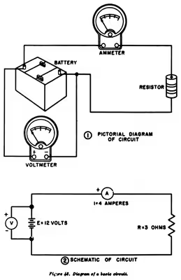
Unlike a block diagram or layout diagram, a circuit diagram shows the actual electrical connections. A drawing meant to depict the physical arrangement of the wires and the components they connect is called artwork or layout, physical design, or wiring diagram.
Circuit diagrams are used for the design (circuit design), construction (such as PCB layout), and maintenance of electrical and electronic equipment.
In computer science, circuit diagrams are useful when visualizing expressions using Boolean algebra.
Symbols
Circuit diagrams are pictures with symbols that have differed from country to country and have changed over time, but are now to a large extent internationally standardized. Simple components often had symbols intended to represent some feature of the physical construction of the device. For example, the symbol for a resistor dates back to the time when that component was made from a long piece of wire wrapped in such a manner as to not produce inductance, which would have made it a coil. These wirewound resistors are now used only in high-power applications, smaller resistors being cast from carbon composition (a mixture of carbon and filler) or fabricated as an insulating tube or chip coated with a metal film. The internationally standardized symbol for a resistor is therefore now simplified to an oblong, sometimes with the value in ohms written inside, instead of the zig-zag symbol. A less common symbol is simply a series of peaks on one side of the line representing the conductor, rather than back-and-forth.
The linkages between leads were once simple crossings of lines. With the arrival of computerized drafting, the connection of two intersecting wires was shown by a crossing of wires with a "dot" or "blob" to indicate a connection. At the same time, the crossover was simplified to be the same crossing, but without a "dot". However, there was a danger of confusing the wires that were connected and not connected in this manner, if the dot was drawn too small or accidentally omitted (e.g. the "dot" could disappear after several passes through a copy machine). As such, the modern practice for representing a 4-way wire connection is to draw a straight wire and then to draw the other wires staggered along it with "dots" as connections (see diagram), so as to form two separate T-junctions that brook no confusion and are clearly not a crossover.
For crossing wires that are insulated from one another, a small semi-circle symbol is commonly used to show one wire "jumping over" the other wire (similar to how jumper wires are used).
A common, hybrid style of drawing combines the T-junction crossovers with "dot" connections and the wire "jump" semi-circle symbols for insulated crossings. In this manner, a "dot" that is too small to see or that has accidentally disappeared can still be clearly differentiated from a "jump".
On a circuit diagram, the symbols for components are labelled with a descriptor or reference designator matching that on the list of parts. For example, C1 is the first capacitor, L1 is the first inductor, Q1 is the first transistor, and R1 is the first resistor. Often the value or type designation of the component is given on the diagram beside the part, but detailed specifications would go on the parts list.
Detailed rules for reference designations are provided in the International standard IEC 61346.
Sign in to keep reading
3 more chapters are free with a Lably account.
Organization
It is a usual (although not universal) convention that schematic drawings are organized on the page from left to right and top to bottom in the same sequence as the flow of the main signal or power path. For example, a schematic for a radio receiver might start with the antenna input at the left of the page and end with the loudspeaker at the right. Positive power supply connections for each stage would be shown towards the top of the page, with grounds, negative supplies, or other return paths towards the bottom. Schematic drawings intended for maintenance may have the principal signal paths highlighted to assist in understanding the signal flow through the circuit. More complex devices have multi-page schematics and must rely on cross-reference symbols to show the flow of signals between the different sheets of the drawing.
Detailed rules for the preparation of circuit diagrams, and other document types used in electrotechnology, are provided in the international standard IEC 61082-1.
Circuit diagrams are often drawn with the same standardized title block and frame as other engineering drawings.
Relay logic line diagrams, also called ladder logic diagrams, use another common standardized convention for organizing schematic drawings, with a vertical power supply rail on the left and another on the right, and components strung between them like the rungs of a ladder.
Artwork
Once the schematic has been made, it is converted into a layout that can be fabricated onto a printed circuit board (PCB). Schematic-driven layout starts with the process of schematic capture. The result is what is known as a rat's nest. The rat's nest is a jumble of wires (lines) criss-crossing each other to their destination nodes. These wires are routed either manually or automatically by the use of electronics design automation (EDA) tools. The EDA tools arrange and rearrange the placement of components and find paths for tracks to connect various nodes. This results in the final layout artwork for the integrated circuit or printed circuit board.
A generalized design flow may be as follows:
- Schematic → schematic capture → netlist → rat's nest → routing → artwork → PCB development and etching → component mounting → testing
Education
Teaching about the functioning of electrical circuits is often on primary and secondary school curricula. Students are expected to understand the rudiments of circuit diagrams and their functioning. Use of diagrammatic representations of circuit diagrams can aid understanding of principles of electricity.
Principles of the physics of circuit diagrams are often taught with the use of analogies, such as comparing functioning of circuits to other closed systems such as water heating systems with pumps being the equivalent to batteries.