

Diffraction-limited system
Optical system with resolution performance at the instrument's theoretical limit
- 10 min read
- 4 chapters

Related on Lably
Through Optics, Microscope and Telescope
The diffraction-limited angular resolution, in radians, of an instrument is proportional to the wavelength of the light being observed, and inversely proportional to the diameter of its objective's entrance aperture. For telescopes with circular apertures, the size of the smallest feature in an image that is diffraction limited is the size of the Airy disk. As one decreases the size of the aperture of a telescopic lens, diffraction proportionately increases. At small apertures, such as f/22, most modern lenses are limited only by diffraction and not by aberrations or other imperfections in the construction.
For microscopic instruments, the diffraction-limited spatial resolution is proportional to the light wavelength, and to the numerical aperture of either the objective or the object illumination source, whichever is smaller.
In astronomy, a diffraction-limited observation is one that achieves the resolution of a theoretically ideal objective in the size of instrument used. However, most observations from Earth are seeing-limited due to atmospheric effects. Optical telescopes on the Earth work at a much lower resolution than the diffraction limit because of the distortion introduced by the passage of light through several kilometres of turbulent atmosphere. Advanced observatories have started using adaptive optics technology, resulting in greater image resolution for faint targets, but it is still difficult to reach the diffraction limit using adaptive optics.
Radio telescopes are frequently diffraction-limited, because the wavelengths they use (from millimeters to meters) are so long that the atmospheric distortion is negligible. Space-based telescopes (such as Hubble, or a number of non-optical telescopes) always work at their diffraction limit, if their design is free of optical aberration.
The beam from a laser with near-ideal beam propagation properties may be described as being diffraction-limited. A diffraction-limited laser beam, passed through diffraction-limited optics, will remain diffraction-limited, and will have a spatial or angular extent essentially equal to the resolution of the optics at the wavelength of the laser.
Calculation of diffraction limit
The Abbe diffraction limit for a microscope
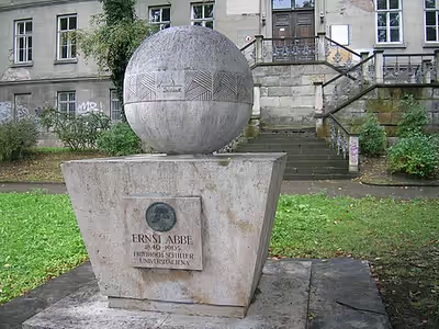
The observation of sub-wavelength structures with microscopes is difficult because of the Abbe diffraction limit. Ernst Abbe first mentioned the diffraction limit in his 1873 paper, page 466: „[…] die physikalische Unterscheidungsgrenze […] hängt allein vom Oeffnungswinkel ab und ist dem Sinus seines halben Betrages proportional“, or "[…] the physical limit of resolution […] depends solely on the aperture angle and is proportional to the sine of half its magnitude". Abbe wrote it in the form of a formula in his 1882 paper, page 461: "The smallest dimensions which are within the reach of a given aperture are indicated with sufficient accuracy by taking the limit of the resolving or separating power of that aperture for periodic or regular structures, i.e. the minimum distance apart at which given elements can be delineated separately with the aperture in question. The numerical expression of that minimum distance is":
- d = 𝜆/2n sin 𝜃 = 𝜆/2NA′
where 𝜆 is the wavelength, n is the refractive index of the medium, and 𝜃 is the semi-angle of the light focused by the optical system. The same formula had been proven by Hermann von Helmholtz in 1874. The portion of the denominator n sin 𝜃 is called the numerical aperture (NA) and can reach about 1.4–1.6 in modern optics, hence the Abbe limit is d = 𝜆/2.8.
Considering green light around 500 nm and a NA of 1, the Abbe limit is roughly d = 𝜆/2 = 250 nm (0.25 μm), which is small compared to most biological cells (1 to 100 μm), but large compared to viruses (100 nm), proteins (10 nm) and less complex molecules (1 nm). To increase the resolution, shorter wavelengths can be used such as UV and X-ray microscopes. These techniques offer better resolution but are expensive, suffer from lack of contrast in biological samples and may damage the sample.
Digital photography
In a digital camera, diffraction effects interact with the effects of the regular pixel grid. The combined effect of the different parts of an optical system is determined by the convolution of the point spread functions (PSF). The point spread function of a diffraction limited circular-aperture lens is simply the Airy disk. The point spread function of the camera, otherwise called the instrument response function (IRF) can be approximated by a rectangle function, with a width equivalent to the pixel pitch. A more complete derivation of the modulation transfer function (derived from the PSF) of image sensors is given by Fliegel. Whatever the exact instrument response function, it is largely independent of the f-number of the lens. Thus at different f-numbers a camera may operate in three different regimes, as follows:
- In the case where the spread of the IRF is small with respect to the spread of the diffraction PSF, in which case the system may be said to be essentially diffraction limited (so long as the lens itself is diffraction limited).
- In the case where the spread of the diffraction PSF is small with respect to the IRF, in which case the system is instrument limited.
- In the case where the spread of the PSF and IRF are similar, in which case both impact the available resolution of the system.
The spread of the diffraction-limited PSF is approximated by the diameter of the first null of the Airy disk:
- d/2 = 1.22𝜆N,
where 𝜆 is the wavelength of the light and N is the f-number of the imaging optics, i.e., 2NA → (2.44N)-1 in the Abbe diffraction limit formula. For instance, for an f/8 lens (N = 8 and NA ≈ 2.5%) and for green light ({{math|𝜆g = 0.5 μm wavelength) light, the focusing spot diameter will be d = 9.76 μm or 19.5𝜆g. This is similar to the pixel size for the majority of commercially available 'full frame' (43 mm sensor diagonal) cameras and so these will operate in regime 3 for f-numbers around 8 (few lenses are close to diffraction limited at f-numbers smaller than 8).
Cameras with smaller sensors will tend to have smaller pixels, but their lenses will be designed for use at smaller f-numbers and it is likely that they will also operate in regime 3 for those f-numbers for which their lenses are diffraction limited. Given the same field of view, pixel count, shutter speed and shot noise SNR (i.e. the same amount of light collected per pixel), a small sensor and a large sensor of equivalent quality will produce the same digital image, with the same amount of blur due to both diffraction and depth of field. The larger sensors do have an advantage in that the lenses for them tend to have larger maximum entrance pupils, which allows, to a larger extent, trading depth of field for less diffraction blur and either more SNR or higher shutter speeds.
Sign in to keep reading
3 more chapters are free with a Lably account.
Obtaining higher resolution
Using special optical systems and digital image processing, it is possible to produce images that have higher resolution (in some specific aspects of the subject, such as color or shape) than would be allowed by simple use of diffraction-limited optics. These largely computational methods offer advantages over other workarounds such as electron microscopy, and have been used to produce reasonably accurate images of individual molecules. Although these techniques improve some aspect of resolution, they generally come at an enormous increase in cost and complexity compared to using a simple light microscope. Usually the technique is only appropriate for a small subset of imaging problems, with several general approaches outlined below.
Extending numerical aperture
The effective resolution of a microscope can be improved by illuminating from the side.
In conventional microscopes such as bright-field or differential interference contrast, this is achieved by using a condenser. Under spatially incoherent conditions, the image is understood as a composite of images illuminated from each point on the condenser, each of which covers a different portion of the object's spatial frequencies. This effectively improves the resolution by, at most, a factor of two.
Simultaneously illuminating from all angles (fully open condenser) drives down interferometric contrast. In conventional microscopes, the maximum resolution (fully open condenser, at N = 1) is rarely used. Further, under partially coherent conditions, the recorded image is often non-linear with object's scattering potential—especially when looking at non-self-luminous (non-fluorescent) objects. To boost contrast, and sometimes to linearize the system, unconventional microscopes (with structured illumination) synthesize the condenser illumination by acquiring a sequence of images with known illumination parameters. Typically, these images are composited to form a single image with data covering a larger portion of the object's spatial frequencies when compared to using a fully closed condenser (which is also rarely used).
Another technique, 4Pi microscopy, uses two opposing objectives to double the effective numerical aperture, effectively halving the diffraction limit, by collecting the forward and backward scattered light. When imaging a transparent sample, with a combination of incoherent or structured illumination, as well as collecting both forward, and backward scattered light it is possible to image the complete scattering sphere.
Unlike methods relying on localization, such systems are still limited by the diffraction limit of the illumination (condenser) and collection optics (objective), although in practice they can provide substantial resolution improvements compared to conventional methods.
Near-field techniques
The diffraction limit is only valid in the far field as it assumes that no evanescent fields reach the detector. Various near-field techniques that operate less than ≈1 wavelength of light away from the image plane can obtain substantially higher resolution. These techniques exploit the fact that the evanescent field contains information beyond the diffraction limit which can be used to construct very high resolution images, in principle beating the diffraction limit by a factor proportional to how well a specific imaging system can detect the near-field signal. For scattered light imaging, instruments such as near-field scanning optical microscopes and nano-FTIR, which are built atop atomic force microscope systems, can be used to achieve up to 10–50 nm resolution. The data recorded by such instruments often requires substantial processing, essentially solving an optical inverse problem for each image.
Metamaterial-based superlenses can image with a resolution better than the diffraction limit by locating the objective lens extremely close (typically hundreds of nanometers) to the object.
In fluorescence microscopy the excitation and emission are typically on different wavelengths. In total internal reflection fluorescence microscopy a thin portion of the sample located immediately on the cover glass is excited with an evanescent field, and recorded with a conventional diffraction-limited objective, improving the axial resolution.
However, because these techniques cannot image beyond 1 wavelength, they cannot be used to image into objects thicker than 1 wavelength which limits their applicability.
Far-field techniques
Far-field imaging techniques are most desirable for imaging objects that are large compared to the illumination wavelength but that contain fine structure. This includes nearly all biological applications in which cells span multiple wavelengths but contain structure down to molecular scales. In recent years several techniques have shown that sub-diffraction limited imaging is possible over macroscopic distances. These techniques usually exploit optical nonlinearity in a material's reflected light to generate resolution beyond the diffraction limit.
Among these techniques, the STED microscope has been one of the most successful. In STED, multiple laser beams are used to first excite, and then quench fluorescent dyes. The nonlinear response to illumination caused by the quenching process in which adding more light causes the image to become less bright generates sub-diffraction limited information about the location of dye molecules, allowing resolution far beyond the diffraction limit provided high illumination intensities are used.
Laser beams
The limits on focusing or collimating a laser beam are very similar to the limits on imaging with a microscope or telescope. The only difference is that laser beams are typically soft-edged beams. This non-uniformity in light distribution leads to a coefficient slightly different from the 1.22 value familiar in imaging. However, the scaling with wavelength and aperture is exactly the same.
The beam quality of a laser beam is characterized by how well its propagation matches an ideal Gaussian beam at the same wavelength. The beam quality factor M squared (M2) is found by measuring the size of the beam at its waist, and its divergence far from the waist, and taking the product of the two, known as the beam parameter product. The ratio of this measured beam parameter product to that of the ideal is defined as M2, so that M2 = 1 describes an ideal beam. The M2 value of a beam is conserved when it is transformed by diffraction-limited optics.
The outputs of many low and moderately powered lasers have M2 values of 1.2 or less, and are essentially diffraction-limited. The M2 factor enters various equations, correcting for the non-ideality of the beam. For example, the smallest possible spot size obtainable by focusing a parallel laser beam by a lens is:
- d = 4𝜆fM2/πD,
where f is the focal length of the lens and D is the beam diameter.
Other waves
The same principle applies to other wave-based sensors, such as radar and the human ear. It can also be generalized to massive particles with the de Broglie wavelength, inversely proportional to the particle momentum, serving as an effective wavelength. For example, an electron at an energy of 10 keV has a wavelength of about 0.01 nm, allowing the electron microscope (SEM or TEM) to achieve high resolution images.