

Diode bridge
Circuit arrangement of four diodes
- 4 min read
- 5 chapters

Related on Lably
Through Diode, Alternating current and Rectifier
When used in its most common application, for conversion of an alternating-current (AC) input into a direct-current (DC) output, it is known as a bridge rectifier. A bridge rectifier provides full-wave rectification from a two-wire AC input, resulting in lower cost and weight as compared to a rectifier with a three-wire input from a transformer with a center-tapped secondary winding.
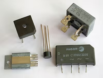
Prior to the availability of integrated circuits, a bridge rectifier was constructed from separate diodes. Since about 1950, a single four-terminal component containing the four diodes connected in a bridge configuration has been available and is now available with various voltage and current ratings.
Diodes are also used in bridge topologies along with capacitors as voltage multipliers.
History
The diode bridge circuit was invented by Karol Pollak and patented in December 1895 in Great Britain and in January 1896 in Germany. Two years later in 1897, Leo Graetz independently published a similar circuit only to discover that the Pollak accumulator factory in Frankfurt am Main was already entering commercial production with its bridge circuit. Nevertheless the circuit is sometimes referred to as a "Graetz circuit" or "Graetz bridge".
Sign in to keep reading
4 more chapters are free with a Lably account.
Current flow
According to the conventional model of current flow, originally established by Benjamin Franklin and still followed by most engineers today, current flows through electrical conductors from the positive to the negative pole (defined as positive flow). In actuality, free electrons in a conductor nearly always flow from the negative to the positive pole. In the vast majority of applications, however, the actual direction of current flow is irrelevant. Therefore, in the discussion below the conventional model is retained.
The fundamental characteristic of a diode is that current can flow only one way through it, which is defined as the forward direction. A diode bridge uses diodes as series components to allow current to pass in the forward direction during the positive part of the AC cycle and as shunt components to redirect current flowing in the reverse direction during the negative part of the AC cycle to the opposite rails.
Rectifier
In the diagrams below, when the input connected to the left corner of the diamond is positive, and the input connected to the right corner is negative, current flows from the upper supply terminal to the right along the red (positive) path to the output and returns to the lower supply terminal through the blue (negative) path.
When the input connected to the left corner is negative, and the input connected to the right corner is positive, current flows from the lower supply terminal to the right along the red (positive) path to the output and returns to the upper supply terminal through the blue (negative) path.
In each case, the upper right output remains positive, and lower right output negative. Since this is true whether the input is AC or DC, this circuit not only produces a DC output from an AC input, it can also provide reverse-polarity protection; that is, it permits normal functioning of DC-powered equipment when batteries have been installed backwards, or when the leads from a DC power source have been reversed, and protects the equipment from potential damage caused by reverse polarity.
Alternatives to the diode-bridge full-wave rectifiers are the center-tapped transformer and double-diode rectifier, and voltage doubler rectifier using two diodes and two capacitors in a bridge topology.
Smoothing circuits
With AC input, the output of a diode bridge (called a full-wave rectifier for this purpose; there is also half-wave rectification, which does not use a diode bridge) is polarized pulsating non-sinusoidal voltage of the same amplitude but twice the frequency of the input. It may be considered as DC voltage upon which is superimposed a very large ripple voltage. This kind of electric power is not very usable, because ripple is dissipated as waste heat in DC circuit components and may cause noise or distortion during circuit operation. So nearly all rectifiers are followed by a series of bandpass or bandstop filters and/or a voltage regulator to convert most or all of the ripple voltage into a smoother and possibly higher DC output. A filter may be as simple as a single sufficiently large capacitor or choke, but most power-supply filters have multiple alternating series and shunt components. When the ripple voltage rises, reactive power is stored in the filter components, reducing the voltage; when the ripple voltage falls, reactive power is discharged from the filter components, raising the voltage. The final stage of rectification may consist of a zener diode-based voltage regulator, which almost completely eliminates any residual ripple.
Polyphase diode bridges
The diode bridge can be generalized to rectify polyphase AC inputs. For example, for a three-phase AC input, a half-wave rectifier consists of three diodes, but a full-wave bridge rectifier consists of six diodes.
A half-wave rectifier may be considered a wye connection (star connection), because it returns the current through the center (neutral) wire. A full-wave rectifier is more like a delta connection, although it can be connected to the three-phase source of either wye or delta and it does not use the center (neutral) wire.