

Voltage
Difference in electric potential between two points in space
- 9 min read
- 8 chapters
- 5 labs on Lably

Learn it on Lably
The voltage between points can be caused by the build-up of electric charge (e.g., a capacitor), and from an electromotive force (e.g., electromagnetic induction in a generator). On a macroscopic scale, a potential difference can be caused by electrochemical processes (e.g., cells and batteries), the pressure-induced piezoelectric effect, photovoltaic effect, and the thermoelectric effect. Since voltage is the difference in electric potential, it is a physical scalar quantity.
A voltmeter can be used to measure the voltage between two points in a system. Often a common reference potential such as the ground of the system is used as one of the points. In this case, voltage is often mentioned at a point without completely mentioning the other measurement point. A voltage can be associated with either a source of energy or the loss, dissipation, or storage of energy.
Definition
The SI unit of work per unit charge is the joule per coulomb, where 1 volt = 1 joule (of work) per 1 coulomb of charge. The old SI definition for volt used power and current; starting in 1990, the Josephson effect was used, and in 2019 physical constants were given defined values for the definition of all SI units.
Voltage is denoted symbolically by , simplified V, especially in English-speaking countries. Internationally, the symbol U is standardized.
The electrochemical potential is the voltage that can be directly measured with a voltmeter. The Galvani potential that exists in structures with junctions of dissimilar materials, is also work per charge but cannot be measured with a voltmeter in the external circuit (see § Galvani potential vs. electrochemical potential).
Voltage is defined so that negatively charged objects are pulled towards higher voltages, while positively charged objects are pulled towards lower voltages. Therefore, the conventional current in a wire or resistor always flows from higher voltage to lower voltage.
Historically, voltage has been referred to using terms like "tension" and "pressure". Even today, the term "tension" is still used, for example within the phrase "high tension" (HT) which is commonly used in the contexts of automotive electronics and systems using thermionic valves (vacuum tubes).
Electrostatics
In electrostatics, the voltage increase from point to some point is given by the change in electrostatic potential from to . By definition, this is:
where is the intensity of the electric field.
In this case, the voltage increase from point A to point B is equal to the work done per unit charge, against the electric field, to move the charge from A to B without causing any acceleration. Mathematically, this is expressed as the line integral of the electric field along that path. In electrostatics, this line integral is independent of the path taken.
Under this definition, any circuit where there are time-varying magnetic fields, such as AC circuits, will not have a well-defined voltage between nodes in the circuit, since the electric force is not a conservative force in those cases. However, at lower frequencies when the electric and magnetic fields are not rapidly changing, this can be neglected (see Electrostatics § Electrostatic approximation).
Electrodynamics
The electric potential can be generalized to electrodynamics, so that differences in electric potential between points are well-defined even in the presence of time-varying fields. However, unlike in electrostatics, the electric field can no longer be expressed only in terms of the electric potential. Furthermore, the potential is no longer uniquely determined up to a constant, and can take significantly different forms depending on the choice of gauge.
In this general case, some authors use the word "voltage" to refer to the line integral of the electric field, rather than to differences in electric potential. In this case, the voltage rise along some path from to is given by:
However, in this case the "voltage" between two points depends on the path taken.
Circuit theory
In circuit analysis and electrical engineering, lumped element models are used to represent and analyze circuits. These elements are idealized and self-contained circuit elements used to model physical components.
When using a lumped element model, it is assumed that the effects of changing magnetic fields produced by the circuit are suitably contained to each element. Under these assumptions, the electric field in the region exterior to each component is conservative, and voltages between nodes in the circuit are well-defined, where
as long as the path of integration does not pass through the inside of any component. The above is the same formula used in electrostatics. This integral, with the path of integration being along the test leads, is what a voltmeter will actually measure.
If uncontained magnetic fields throughout the circuit are not negligible, then their effects can be modelled by adding mutual inductance elements. In the case of a physical inductor though, the ideal lumped representation is often accurate. This is because the external fields of inductors are generally negligible, especially if the inductor has a closed magnetic path. If external fields are negligible, we find that
is path-independent, and there is a well-defined voltage across the inductor's terminals. This is the reason that measurements with a voltmeter across an inductor are often reasonably independent of the placement of the test leads.
Sign in to keep reading
7 more chapters are free with a Lably account.
Volt
The volt (symbol: V) is the derived unit for electric potential, voltage, and electromotive force. The volt is named in honour of the Italian physicist Alessandro Volta (1745–1827), who invented the voltaic pile, possibly the first chemical battery.
Hydraulic analogy
A simple analogy for an electric circuit is water flowing in a closed circuit of pipework, driven by a mechanical pump. This can be called a "water circuit". The potential difference between two points corresponds to the pressure difference between two points. If the pump creates a pressure difference between two points, then water flowing from one point to the other will be able to do work, such as driving a turbine. Similarly, work can be done by an electric current driven by the potential difference provided by a battery. For example, the voltage provided by a sufficiently-charged automobile battery can "push" a large current through the windings of an automobile's starter motor. If the pump is not working, it produces no pressure difference, and the turbine will not rotate. Likewise, if the automobile's battery is very weak or "dead" (or "flat"), then it will not turn the starter motor.
The hydraulic analogy is a useful way of understanding many electrical concepts. In such a system, the work done to move water is equal to the "pressure drop" (compare p.d.) multiplied by the volume of water moved. Similarly, in an electrical circuit, the work done to move electrons or other charge carriers is equal to "electrical pressure difference" multiplied by the quantity of electrical charges moved. In relation to "flow", the larger the "pressure difference" between two points (potential difference or water pressure difference), the greater the flow between them (electric current or water flow). (See "electric power".)
Applications
Specifying a voltage measurement requires explicit or implicit specification of the points across which the voltage is measured. When using a voltmeter to measure voltage, one electrical lead of the voltmeter must be connected to the first point, one to the second point.
A common use of the term "voltage" is in describing the voltage dropped across an electrical device (such as a resistor). The voltage drop across the device can be understood as the difference between measurements at each terminal of the device with respect to a common reference point (or ground). The voltage drop is the difference between the two readings. Two points in an electric circuit that are connected by an ideal conductor without resistance and not within a changing magnetic field have a voltage of zero. Any two points with the same potential may be connected by a conductor and no current will flow between them.
Addition of voltages
The voltage between A and C is the sum of the voltage between A and B and the voltage between B and C. The various voltages in a circuit can be computed using Kirchhoff's circuit laws.
When talking about alternating current (AC) there is a difference between instantaneous voltage and average voltage. Instantaneous voltages can be added for direct current (DC) and AC, but average voltages can be meaningfully added only when they apply to signals that all have the same frequency and phase.
Measuring instruments
Instruments for measuring voltages include the voltmeter, the potentiometer, and the oscilloscope. Analog voltmeters, such as moving-coil instruments, work by measuring the current through a fixed resistor, which, according to Ohm's law, is proportional to the voltage across the resistor. The potentiometer works by balancing the unknown voltage against a known voltage in a bridge circuit. The cathode-ray oscilloscope works by amplifying the voltage and using it to deflect an electron beam from a straight path, so that the deflection of the beam is proportional to the voltage.
Typical voltages
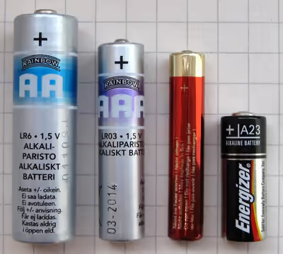
A common voltage for flashlight batteries is 1.5 volts (DC). A common voltage for automobile batteries is 12 volts (DC).
Common voltages supplied by power companies to consumers are 110 to 120 volts (AC) in North America and 220 to 240 volts (AC) in most of Europe. The voltage in electric power transmission lines used to distribute electricity from power stations can be several hundred times greater than consumer voltages, typically 110 to 1200 kV (AC).
The voltage used in overhead lines to power railway locomotives is between 12 kV and 50 kV (AC) or between 0.75 kV and 3 kV (DC).
Galvani potential vs. electrochemical potential
Inside a conductive material, the energy of an electron is affected not only by the average electric potential but also by the specific thermal and atomic environment that it is in. When a voltmeter is connected between two different types of metal, it measures not the electrostatic potential difference, but instead something else that is affected by thermodynamics. The quantity measured by a voltmeter is the negative of the difference of the electrochemical potential of electrons (Fermi level) divided by the electron charge and commonly referred to as the voltage difference, while the pure unadjusted electrostatic potential (not measurable with a voltmeter) is sometimes called Galvani potential. The terms "voltage" and "electric potential" are ambiguous in that, in practice, they can refer to either of these in different contexts.
History
The term electromotive force was first used by Volta in a letter to Giovanni Aldini in 1798, and first appeared in a published paper in 1801 in Annales de chimie et de physique. Volta meant by this a force that was not an electrostatic force, specifically, an electrochemical force. The term was taken up by Michael Faraday in connection with electromagnetic induction in the 1820s. However, a clear definition of voltage and method of measuring it had not been developed at this time. Volta distinguished electromotive force (emf) from tension (potential difference): the observed potential difference at the terminals of an electrochemical cell when it was open circuit must exactly balance the emf of the cell so that no current flowed.