

Ground (electricity)
Reference point in an electrical circuit from which voltages are measured
- 23 min read
- 5 chapters

Learn it on Lably
A protective earth conductor (PE conductor) is a conductor that is used for electrical bonding, that is, connecting an electrical equipment from its exposed and conductive but normally unenergized part to common ground. If the conductor is a wire, it is also called ground wire or earth wire. Ground wire is often used for lower voltage systems and is often colored green, or green and yellow, per standard. Electrical bonding can protect users from electrical shock hazards. If internal insulation fails and the equipment is turned on, the exposed conductive parts may have dangerous voltages. Connection of exposed conductive parts to a PE conductor provides a low-impedance path for current to flow back to the incoming neutral. This results in a fault and allows circuit breakers (or RCDs) to interrupt power supply. The current that flows through the low-impedance path is high and will usually trip the breaker or melt the safety fuse if any. Even if the circuit does not break due to failures, the current still only flows mainly through the PE conductor instead of the user upon touching the exposed conductive part. A PE conductor is an essential part of the safety provided by the earthing system. A safety ground is a loose term that refers to a common ground that is used for safety purposes.
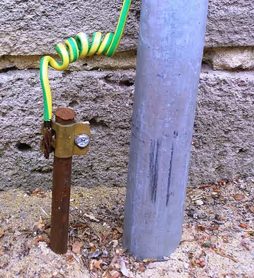
Connection to earth ground limits the build-up of static electricity. This connection is crucial for safety when handling flammable products or electrostatic-sensitive devices. In a large-scale electrical system, a piece of conducting material, called grounding electrode or earthing electrode, is buried in the soil to act as an earth ground. A grounding electrode conductor or ground conductor is a conductor that connects an electrical equipment to the grounding electrode. In some telegraph and power transmission circuits, the physical ground (an earth ground) itself can be used as one conductor of the circuit, saving the cost of installing a separate return conductor (see single-wire earth return and earth-return telegraph). In an electric power system, the neutral is connected to earth ground, close to the point of entry.
For measurement purposes, the ground of the Earth, having a reasonably constant potential, serves as a reference ground against which other potentials can be measured. An electrical ground system should have an appropriate current-carrying capability to serve as an adequate zero-voltage reference level. Circuits in portable electronic devices, such as cell phones and media players, as well as circuits in vehicles, have a reference ground (also called chassis ground in those cases).
In electronic circuit theory, a signal ground is the common ground and reference ground for electric signal; and a power ground is the common ground for power current. The signal ground and power ground may be connected. There is usually a large conductor attached to one side of the power supply (such as the "ground plane" on a printed circuit board), which serves as the common ground, the common return path for current from many different components in the circuit. The signal ground and power ground are usually assumed to be an earth ground and idealized as an infinite source or sink for charge, which can absorb an unlimited amount of current without changing its potential. Where a physical ground connection has a significant resistance, the approximation of zero potential is no longer valid (no longer a valid reference ground). Stray voltages or earth potential rise effects will occur, which may create noise in signals or produce an electric shock hazard if large enough.
Electric power system
Building wiring installations
Electrical power distribution systems are often connected to earth ground to limit the voltage that can appear on distribution circuits. A distribution system insulated from earth ground may attain a high potential due to transient voltages caused by static electricity or accidental contact with higher potential circuits. An earth ground connection of the system dissipates such potentials and limits the rise in voltage of the grounded system.
In a mains electricity (AC power) wiring installation, the term ground conductor typically refers to two different conductors or conductor systems as listed below:
Equipment bonding conductors or equipment ground conductors (EGC) provide a low-impedance path between normally non-current-carrying metallic parts of equipment and one of the conductors of that electrical system's source. If any exposed metal part should become energized (fault), such as by a frayed or damaged insulator, it creates a short circuit, causing the overcurrent device (circuit breaker or fuse) to open, clearing (disconnecting) the fault. This action occurs regardless of whether there is a connection to the physical ground; the physical ground itself has no role in this fault-clearing process since current must return to its source; however, the sources are very frequently connected to the physical ground. (see Kirchhoff's circuit laws). By bonding (interconnecting) all exposed non-current carrying metal objects together, as well as to other metallic objects such as pipes or structural steel, they should remain near the same voltage potential, thus reducing the chance of a shock. This is especially important in bathrooms where one may be in contact with several different metallic systems such as supply and drain pipes and appliance frames. When a conductive system is to be electrically connected to the physical ground, one puts the equipment bonding conductor and the grounding electrode conductor at the same potential (for example, see §Metal water pipe as grounding electrode below).
A grounding electrode conductor (GEC) is used to connect the system grounded ("neutral") conductor, or the equipment to a grounding electrode, or a point on the grounding electrode system. This is called "system grounding" and most electrical systems are required to be grounded. The US NEC and the UK's BS 7671 list systems that are required to be grounded. According to the NEC, the purpose of connecting an electrical system to the physical ground is to limit the voltage imposed by lightning events and contact with higher voltage lines. In the past, water supply pipes were used as grounding electrodes, but due to the increased use of plastic pipes, which are poor conductors, the use of a specific grounding electrode is often mandated by regulating authorities. The same type of ground applies to radio antennas and to lightning protection systems.
Permanently installed electrical equipment, unless not required to, has permanently connected grounding conductors. Portable electrical devices with metal cases may have them connected to earth ground by a pin on the attachment plug (see AC power plugs and sockets). The size of power grounding conductors is usually regulated by local or national wiring regulations.
Bonding
Bonding is the practice of intentionally electrically connecting metallic items not designed to carry electricity. This brings all the bonded items to the same electrical potential as a protection from electrical shock. The bonded items can then be connected to ground to eliminate foreign voltages.
Earthing systems
In electricity supply systems, an earthing system or grounding system defines the electrical potential of the conductors relative to that of the Earth's conductive surface. The choice of earthing system has implications for the safety and electromagnetic compatibility of the power supply. Regulations for earthing systems vary considerably between different countries.
A functional earth connection serves more than protecting against electrical shock, as such a connection may carry current during the normal operation of a device. Such devices include surge suppression, electromagnetic-compatibility filters, some types of antennas, and various measurement instruments. Generally the protective earth system is also used as a functional earth, though this requires care.
Impedance grounding
Distribution power systems may be solidly grounded, with one circuit conductor directly connected to an earth grounding electrode system. Alternatively, some amount of electrical impedance may be connected between the distribution system and ground, to limit the current that can flow to earth. The impedance may be a resistor, or an inductor (coil). In a high-impedance grounded system, the fault current is limited to a few amperes (exact values depend on the voltage class of the system); a low-impedance grounded system will permit several hundred amperes to flow on a fault. A large solidly grounded distribution system may have tens of thousands of amperes of ground fault current.
In a polyphase AC system, the instantaneous vector sum of the phases is zero. This neutral point is commonly used to refer the phase voltages to earth ground instead of connecting one of the phase conductors to earth. Any Δ-Y (delta-wye) connected transformer may be used for the purpose. A nine winding transformer (a "zig zag" transformer) may be used to balance the phase currents of a delta connected source with an unbalanced load.
Low-resistance grounding systems use a neutral grounding resistor (NGR) to limit the fault current to 25 A or greater. Low resistance grounding systems will have a time rating (say, 10 seconds) that indicates how long the resistor can carry the fault current before overheating. A ground fault protection relay must trip the breaker to protect the circuit before overheating of the resistor occurs.
High-resistance grounding (HRG) systems use an NGR to limit the fault current to 25 A or less. They have a continuous rating, and are designed to operate with a single-ground fault. This means that the system will not immediately trip on the first ground fault. If a second ground fault occurs, a ground fault protection relay must trip the breaker to protect the circuit. On an HRG system, a sensing resistor is used to continuously monitor system continuity. If an open-circuit is detected (e.g., due to a broken weld on the NGR), the monitoring device will sense voltage through the sensing resistor and trip the breaker. Without a sensing resistor, the system could continue to operate without ground protection (since an open circuit condition would mask the ground fault) and transient overvoltages could occur.
Ungrounded systems
Where the danger of electric shock is high, special ungrounded power systems may be used to minimize possible leakage current to ground. Examples of such installations include patient care areas in hospitals, where medical equipment is directly connected to a patient and must not permit any power-line current to pass into the patient's body. Medical systems include monitoring devices to warn of any increase of leakage current. On wet construction sites or in shipyards, isolation transformers may be provided so that a fault in a power tool or its cable does not expose users to shock hazard.
Circuits used to feed sensitive audio/video production equipment or measurement instruments may be fed from an isolated ungrounded technical power system to limit the injection of noise from the power system.
Power transmission
In single-wire earth return (SWER) AC electrical distribution systems, costs are saved by using just a single high voltage conductor for the power grid, while routing the AC return current through the earth. This system is mostly used in rural areas where large earth currents will not otherwise cause hazards.
Some high-voltage direct-current (HVDC) power transmission systems use the ground as second conductor. This is especially common in schemes with submarine cables, as sea water is a good conductor. Buried grounding electrodes are used to make the connection to the earth. The site of these electrodes must be chosen carefully to prevent electrochemical corrosion on underground structures.
A particular concern in design of electrical substations is earth potential rise. When very large fault currents are injected into the earth, the area around the point of injection may rise to a high potential with respect to points distant from it. This is due to the limited finite conductivity of the layers of soil in the earth of the substation. The gradient of the voltage (the change in voltage across the distance to the injection point) may be so high that two points on the ground may be at significantly different potentials. This gradient creates a hazard to anyone standing on the earth in an area of the electrical substation that is insufficiently insulated from ground. Pipes, rails, or communication wires entering a substation may see different ground potentials inside and outside the substation, creating a dangerous touch voltage for unsuspecting persons who might touch those pipes, rails, or wires. This problem is alleviated by creating a low-impedance equipotential bonding plane installed in accordance with IEEE 80, within the substation. This plane eliminates voltage gradients and ensures that any fault is cleared within three voltage cycles.
Lightning protection systems
Lightning protection systems are designed to mitigate the effects of lightning through connection to extensive grounding systems that provide a large surface area connection to earth. The large area is required to dissipate the high current of a lightning strike without damaging the system conductors by excess heat. Since lightning strikes are pulses of energy with very high frequency components, grounding systems for lightning protection tend to use short straight runs of conductors to reduce the self-inductance and skin effect.
Ground mat
In an electrical substation a ground mat, grounding mat, earth mat or earthing mat is a mesh of conductive material installed at places where a person would stand to operate a switch or other apparatus; it is bonded to the local supporting metal structure and to the handle of the switchgear, so that the operator will not be exposed to a high differential voltage due to a fault in the substation.
In the vicinity of electrostatic sensitive devices, a ground mat is used to ground static electricity generated by people and moving equipment. There are two types used in static control: Static Dissipative Mats, and Conductive Mats.
A static dissipative mat that rests on a conductive surface (commonly the case in military facilities) are typically made of three layers (3-ply) with static dissipative vinyl layers surrounding a conductive substrate which is electrically attached to ground. For commercial uses, static dissipative rubber mats are traditionally used that are made of two layers (2-ply) with a tough solder resistant top static dissipative layer that makes them last longer than the vinyl mats, and a conductive rubber bottom. Conductive mats are made of carbon and used only on floors for the purpose of drawing static electricity to ground as quickly as possible. Normally conductive mats are made with cushioning for standing and are referred to as "anti-fatigue" mats.
For a static dissipative mat to be reliably grounded it must be attached to a path to ground. Normally, both the mat and the wrist strap are connected to ground by using a common point ground system (CPGS).
In computer repair shops and electronics manufacturing, workers must be grounded before working on devices sensitive to voltages capable of being generated by humans. For that reason static dissipative mats can be and are also used on production assembly floors as "floor runner" along the assembly line to draw static generated by people walking up and down.
Sign in to keep reading
4 more chapters are free with a Lably account.
Electronic circuit
Signal grounds serve as return paths for signals and power (at extra-low voltages, less than about 50 V) within equipment, and on the signal interconnections between equipment. Many electronic designs feature a single return that acts as a reference for all signals. Power and signal grounds often get connected, usually through the metal case of the equipment. Designers of printed circuit boards must take care in the layout of electronic systems so that high-power or rapidly switching currents in one part of a system do not inject noise into low-level sensitive parts of a system due to some common impedance in the grounding traces of the layout.
Circuit ground versus earth
Voltage is defined as the difference of electric potentials between points in an electric field. A voltmeter is used to measure the potential difference between some point and a convenient, but otherwise arbitrary reference point. This common reference point is denoted "ground" and is designated as having a nominal zero potential. Signals are defined with respect to signal ground, which may be connected to a power ground. A system where the system ground is not connected to another circuit or to earth (in which there may still be AC coupling between those circuits) is often referred to as a floating ground, and may correspond to Class 0 or Class II appliances.
Functional grounds
Some devices require a connection to the mass of earth to function correctly, as distinct from any purely protective role. Such a connection is known as a functional earth – for example some long wavelength antenna structures require a functional earth connection, which generally should not be indiscriminately connected to the supply protective earth, as the introduction of transmitted radio frequencies into the electrical distribution network is both illegal and potentially dangerous. Because of this separation, a purely functional ground should not normally be relied upon to perform a protective function. To avoid accidents, such functional grounds are normally wired in white, cream or pink cable, and not green or green/yellow.
Separating low signal ground from a noisy ground
In television stations, recording studios, and other installations where signal quality is critical, a special signal ground known as a "technical ground" (or "technical earth", "special earth", and "audio earth") is often installed, to prevent ground loops. This is basically the same thing as an AC power ground, but no general appliance ground wires are allowed any connection to it, as they may carry electrical interference. For example, only audio equipment is connected to the technical ground in a recording studio. In most cases, the studio's metal equipment racks are all joined with heavy copper cables (or flattened copper tubing or busbars) and similar connections are made to the technical ground. Great care is taken that no general chassis grounded appliances are placed on the racks, as a single AC ground connection to the technical ground will destroy its effectiveness. For particularly demanding applications, the main technical ground may consist of a heavy copper pipe, if necessary fitted by drilling through several concrete floors, such that all technical grounds may be connected by the shortest possible path to a grounding rod in the basement.
Telegraphy
Earth-return telegraph
Long-distance electromagnetic telegraph systems from 1820 onwards used two or more wires to carry the signal and return currents. It was discovered by German scientist C.A. von Steinheil in 1836–1837, that the ground could be used as the return path to complete the circuit, making the return wire unnecessary. Steinheil was not the first to do this, but he was not aware of earlier experimental work, and he was the first to do it on an in-service telegraph, thus making the principle known to telegraph engineers generally. However, there were problems with this system, exemplified by the transcontinental telegraph line constructed in 1861 by the Western Union Company between St. Joseph, Missouri, and Sacramento, California. During dry weather, the ground connection often developed a high resistance, requiring water to be poured on the ground rod to enable the telegraph to work or phones to ring.
In the late nineteenth century, when telephony began to replace telegraphy, it was found that the currents in the earth induced by power systems, electric railways, other telephone and telegraph circuits, and natural sources including lightning caused unacceptable interference to the audio signals, and the two-wire or 'metallic circuit' system was reintroduced around 1883.
Radio frequency ground
Certain types of radio antennas (or their feedlines) require a connection to ground that functions adequately at radio frequencies. This type of ground is called a radio frequency ground. In general, a radio transmitter, its power source, and its antenna will require three functionally different grounds:
- A lightning safety ground (perhaps several) that discharges lightning strikes on an outdoor antenna, and separately one that diverts residual strike current from entering the house / radio shack / radio equipment
- An electrical power safety ground, provided by the ground connection at the electrical outlet
- A radio frequency ground that establishes a low-resistance return path for the electrical field produced by the antenna during the process of creating radiated waves.
Although some of these grounds might be combined, and should be connected at exactly one point, only the last type of ground is covered in this section. Lightning safety grounding (1) is covered in the following section, not here. The electrical safety ground (2) was discussed in previous sections and is unsuitable for radio purposes, although required for the power supply. The radio frequency ground (3) is the topic of this section.
Since the radio frequencies of the current in antennas are far higher than the 50 or 60 Hz frequency of the power line, radio grounding systems use different principles than AC power grounding. The "protective earth" (PE) safety ground wires in AC utility building wiring were not designed for, and cannot be used as an adequate substitute for an RF ground. The long utility ground wires have high impedance at certain frequencies. In the case of a transmitter, the RF current flowing through the ground wires can radiate radio frequency interference and induce hazardous voltages on grounded metal parts of other appliances, so separate ground systems are used.
Monopole antennas operating at lower frequencies, below 20 MHz, use the surface of the Earth as a part of the antenna, as a conductive plane to reflect the radio waves and provide a return path for electric fields extending from the antenna. Types of earth-grounded monopoles include the mast radiator used by AM radio stations, the 'T' and inverted 'L' antenna, and umbrella antenna. The feedline from the transmitter is connected between the antenna and ground, so it requires a grounding (earthing) system under the antenna to make contact with the soil to collect the return current. The ground system also functions as a capacitor plate, to receive the displacement current from the antenna and return it to the ground side of the transmitter's feedline, so it is preferably located directly under the antenna. In receivers and low efficiency / low power transmitters, the ground connection can be as simple as one or several metal rods or stakes driven into the soil, or an electrical connection to a building's metal water piping which extends into the earth. However, in transmitting antennas the ground system carries the full output current of the transmitter, so the resistance of an inadequate ground contact can be a major loss of transmitter power.
Medium to high power transmitters usually have an extensive ground system consisting of bare copper cables buried in the earth under the antenna, to lower resistance. Since for the omnidirectional antennas used on these bands the Earth currents travel radially toward the ground point from all directions, the grounding system usually consists of a radial pattern of buried cables extending outward under the antenna in all directions, connected together to the ground side of the transmitter's feedline at a terminal next to the base of the antenna called a radial ground system.
The transmitter power lost in the ground resistance, and so the efficiency of the antenna, depends on the soil conductivity. This varies widely; marshy ground or ponds, particularly salt water, provide the lowest resistance ground, while dry rocky or sandy soil are the highest. The power loss per square meter in the ground is proportional to the square of the transmitter current density flowing in the earth. The current density, and power dissipated, increases the closer one gets to the ground terminal at the base of the antenna, so the radial ground system can be thought of as providing a higher conductivity medium, copper, for the ground current to flow through, in the parts of the ground carrying high current density, to reduce power losses.
Design
A standard ground system widely used for mast radiator broadcasting antennas operating in the MF and LF bands consists of 120 equally-spaced, buried, radial ground wires extending out one quarter of a wavelength (, or 90 electrical degrees) from the antenna base. AWG 8 to AWG 10 soft-drawn copper wire is typically used, buried 4–10 in (100–250 mm) deep. For AM broadcast band antennas this requires a circular land area extending from the mast 47–136 meters (154–446 ft). This is usually planted with grass, which is kept mowed short, as tall grass can increase power loss in certain circumstances. If the land area available is too limited for such long radials, they can in many cases be adequately replaced by a greater number of shorter radials, or a smaller number of longer radials.
In transmitting antennas a second cause of power wastage is dielectric power losses of the electric field (displacement current) of the antenna passing through the earth to reach the ground wires. For antennas near a half-wavelength high (180 electrical degrees) the antenna has a voltage maximum (antinode) near its base, which results in strong electric fields in the earth above the ground wires near the mast where the displacement current enters the ground. To reduce this loss these antennas often use a conductive copper ground screen under the antenna connected to the buried ground wires, either lying on the ground or elevated a few feet, to shield the ground from the electric field.
In a few cases where rocky or sandy soil has too high a resistance for a buried ground, a counterpoise is used. This is a radial network of wires similar to that in a buried ground system, but lying on the surface or suspended a few feet above the ground. It acts as a capacitor plate, capacitively coupling the feedline to conductive layers of the soil.
Electrically short antennas
At lower frequencies the resistance of the ground system is a more critical factor because of the small radiation resistance of the antenna. In the LF and VLF bands, construction height limitations require that electrically short antennas be used, shorter than the fundamental resonant length of one quarter of a wavelength (). A quarter wave monopole has a radiation resistance of around 25~36 ohms, but below the resistance decreases with the square of the ratio of height to wavelength. The power fed to an antenna is split between the radiation resistance, which represents power emitted as radio waves, the desired function of the antenna, and the ohmic resistance of the ground system, which results in power wasted as heat. As the wavelength gets longer in relation to antenna height, the radiation resistance of the antenna decreases so the ground resistance constitutes a larger proportion of the input resistance of the antenna and consumes more of the transmitter power. Antennas in the VLF band often have a resistance of less than 1 ohm, and even with extremely low resistance ground systems 50% to 90% of the transmitter power may be wasted in the ground system.
Isolation
Isolation is a mechanism that defeats grounding. It is frequently used with low-power consumer devices, and when engineers, hobbyists, or repairmen are working on circuits that would normally be operated using the power line voltage. Isolation can be accomplished by simply placing a "1:1 wire ratio" transformer with an equal number of turns between the device and the regular power service, but applies to any type of transformer using two or more coils electrically insulated from each other.
For an isolated device, touching a single powered conductor does not cause a severe shock, because there is no path back to the other conductor through the ground. However, shocks and electrocution may still occur if both poles of the transformer are contacted by bare skin. Previously it was suggested that repairmen "work with one hand behind their back" to avoid touching two parts of the device under test at the same time, thereby preventing a current from crossing through the chest and interrupting cardiac rhythms or causing cardiac arrest.
Generally every AC power line transformer acts as an isolation transformer, and every step up or down has the potential to form an isolated circuit. However, this isolation would prevent failed devices from blowing fuses when shorted to their ground conductor. The isolation that could be created by each transformer is defeated by always having one leg of the transformers grounded, on both sides of the input and output transformer coils. Power lines also typically ground one specific wire at every pole, to ensure current equalization from pole to pole if a short to ground is occurring.
In the past, grounded appliances have been designed with internal isolation to a degree that allowed the simple disconnection of ground by cheater plugs without apparent problem (a dangerous practice, since the safety of the resulting floating equipment relies on the insulation in its power transformer). Modern appliances however often include power entry modules which are designed with deliberate capacitive coupling between the AC power lines and chassis, to suppress electromagnetic interference. This results in a significant leakage current from the power lines to ground. If the ground is disconnected by a cheater plug or by accident, the resulting leakage current can cause mild shocks, even without any fault in the equipment. Even small leakage currents are a significant concern in medical settings, as the accidental disconnection of ground can introduce these currents into sensitive parts of the human body. As a result, medical power supplies are designed to have low capacitance.
Class II appliances and power supplies (such as cell phone chargers) do not provide any ground connection, and are designed to isolate the output from input. Safety is ensured by double-insulation, so that two failures of insulation are required to cause a shock.