

Photomultiplier tube
Fast, high sensitivity, low noise electronic photon detector
- 17 min read
- 4 chapters

Related on Lably
Through Light, Electromagnetic spectrum and Decibel
The combination of high gain, low noise, high frequency response or, equivalently, ultra-fast response, and large area of collection has maintained photomultipliers an essential place in low light level spectroscopy, confocal microscopy, Raman spectroscopy, fluorescence spectroscopy, nuclear and particle physics, astronomy, medical diagnostics including blood tests, medical imaging, motion picture film scanning (telecine), radar jamming, and high-end image scanners known as drum scanners. Elements of photomultiplier technology, when integrated differently, are the basis of night vision devices. Research that analyzes light scattering, such as the study of polymers in solution, often uses a laser and a PMT to collect the scattered light data.
Semiconductor devices, particularly silicon photomultipliers and avalanche photodiodes, are alternatives to classical photomultipliers; however, photomultipliers are uniquely well-suited for applications requiring low-noise, high-sensitivity detection of light that is imperfectly collimated.
Structure and operating principles
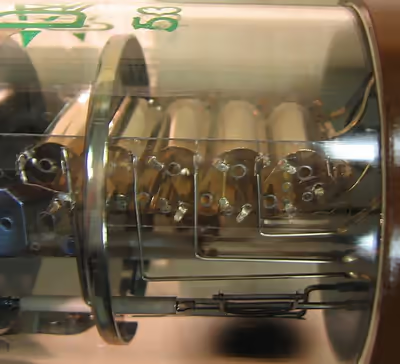
Photomultipliers are typically constructed with an evacuated glass housing (using an extremely tight and durable glass-to-metal seal like other vacuum tubes), containing a photocathode, several dynodes, and an anode. Incident photons strike the photocathode material, which is usually a thin vapor-deposited conducting layer on the inside of the entry window of the device. Electrons are ejected from the surface as a consequence of the photoelectric effect. These electrons are directed by the focusing electrode toward the electron multiplier, where electrons are multiplied by the process of secondary emission.
The electron multiplier consists of a number of electrodes called dynodes. Each dynode is held at a more positive potential, by ≈100 Volts, than the preceding one. A primary electron leaves the photocathode with the energy of the incoming photon, or about 3 eV for "blue" photons, minus the work function of the photocathode. A small group of primary electrons is created by the arrival of a group of initial photons. (In Fig. 1, the number of primary electrons in the initial group is proportional to the energy of the incident high energy gamma ray.) The primary electrons move toward the first dynode because they are accelerated by the electric field. They each arrive with ≈100 eV kinetic energy imparted by the potential difference. Upon striking the first dynode, more low energy electrons are emitted, and these electrons are in turn accelerated toward the second dynode. The geometry of the dynode chain is such that a cascade occurs with an exponentially-increasing number of electrons being produced at each stage. For example, if at each stage an average of 5 new electrons are produced for each incoming electron, and if there are 12 dynode stages, then at the last stage one expects for each primary electron about 512 ≈ 108 electrons. This last stage is called the anode. This large number of electrons reaching the anode results in a sharp current pulse that is easily detectable, for example on an oscilloscope, signaling the arrival of the photon(s) at the photocathode ≈50 nanoseconds earlier.
The necessary distribution of voltage along the series of dynodes is created by a voltage divider chain, as illustrated in Fig. 2. In the example, the photocathode is held at a negative high voltage on the order of 1000 V, while the anode is very close to ground potential. The capacitors across the final few dynodes act as local reservoirs of charge to help maintain the voltage on the dynodes while electron avalanches propagate through the tube. Many variations of design are used in practice; the design shown is merely illustrative.
There are two common photomultiplier orientations, the head-on or end-on (transmission mode) design, as shown above, where light enters the flat, circular top of the tube and passes the photocathode, and the side-on design (reflection mode), where light enters at a particular spot on the side of the tube, and impacts on an opaque photocathode. The side-on design is used, for instance, in the type 931, the first mass-produced PMT. Besides the different photocathode materials, performance is also affected by the transmission of the window material that the light passes through, and by the arrangement of the dynodes. Many photomultiplier models are available having various combinations of these, and other, design variables. The manufacturers manuals provide the information needed to choose an appropriate design for a particular application.
Sign in to keep reading
3 more chapters are free with a Lably account.
History
The invention of the photomultiplier is predicated upon two prior achievements, the separate discoveries of the photoelectric effect and of secondary emission.
Photoelectric effect
The first demonstration of the photoelectric effect was carried out in 1887 by Heinrich Hertz using ultraviolet light. Significant for practical applications, Elster and Geitel two years later demonstrated the same effect using visible light striking alkali metals (potassium and sodium). The addition of caesium, another alkali metal, has permitted the range of sensitive wavelengths to be extended towards longer wavelengths in the red portion of the visible spectrum.
Historically, the photoelectric effect is associated with Albert Einstein, who relied upon the phenomenon to establish the fundamental principle of quantum mechanics in 1905, an accomplishment for which Einstein received the 1921 Nobel Prize. It is worthwhile to note that Heinrich Hertz, working 18 years earlier, had not recognized that the kinetic energy of the emitted electrons is proportional to the frequency but independent of the optical intensity. This fact implied a discrete nature of light, i.e. the existence of quanta, for the first time.
Secondary emission
The phenomenon of secondary emission (the ability of electrons in a vacuum tube to cause the emission of additional electrons by striking an electrode) was, at first, limited to purely electronic phenomena and devices (which lacked photosensitivity). In 1899 the effect was first reported by Villard. In 1902, Austin and Starke reported that the metal surfaces impacted by electron beams emitted a larger number of electrons than were incident. The application of the newly discovered secondary emission to the amplification of signals was only proposed after World War I by Westinghouse scientist Joseph Slepian in a 1919 patent.
The race towards a practical electronic television camera
The ingredients for inventing the photomultiplier were coming together during the 1920s as the pace of vacuum tube technology accelerated. The primary goal for many, if not most, workers was the need for a practical television camera technology. Television had been pursued with primitive prototypes for decades prior to the 1934 introduction of the first practical video camera (the iconoscope). Early prototype television cameras lacked sensitivity. Photomultiplier technology was pursued to enable television camera tubes, such as the iconoscope and (later) the orthicon, to be sensitive enough to be practical. So the stage was set to combine the dual phenomena of photoemission (i.e., the photoelectric effect) with secondary emission, both of which had already been studied and adequately understood, to create a practical photomultiplier.
First photomultiplier, single-stage (early 1934)
The first documented photomultiplier demonstration dates to the early 1934 accomplishments of an RCA group based in Harrison, NJ. Harley Iams and Bernard Salzberg were the first to integrate a photoelectric-effect cathode and single secondary emission amplification stage in a single vacuum envelope and the first to characterize its performance as a photomultiplier with electron amplification gain. These accomplishments were finalized prior to June 1934 as detailed in the manuscript submitted to Proceedings of the Institute of Radio Engineers (Proc. IRE). The device consisted of a semi-cylindrical photocathode, a secondary emitter mounted on the axis, and a collector grid surrounding the secondary emitter. The tube had a gain of about eight and operated at frequencies well above 10 kHz.
Magnetic photomultipliers (mid 1934–1937)
Higher gains were sought than those available from the early single-stage photomultipliers. However, it is an empirical fact that the yield of secondary electrons is limited in any given secondary emission process, regardless of acceleration voltage. Thus, any single-stage photomultiplier is limited in gain. At the time the maximum first-stage gain that could be achieved was approximately 10 (very significant developments in the 1960s permitted gains above 25 to be reached using negative electron affinity dynodes). For this reason, multiple-stage photomultipliers, in which the photoelectron yield could be multiplied successively in several stages, were an important goal. The challenge was to cause the photoelectrons to impinge on successively higher-voltage electrodes rather than to travel directly to the highest voltage electrode. Initially this challenge was overcome by using strong magnetic fields to bend the electrons' trajectories. Such a scheme had earlier been conceived by inventor J. Slepian by 1919 (see above). Accordingly, leading international research organizations turned their attention towards improving photomultipliers to achieve higher gain with multiple stages.
In the USSR, RCA-manufactured radio equipment was introduced on a large scale by Joseph Stalin to construct broadcast networks, and the newly formed All-Union Scientific Research Institute for Television was gearing up a research program in vacuum tubes that was advanced for its time and place. Numerous visits were made by RCA scientific personnel to the USSR in the 1930s, prior to the Cold War, to instruct the Soviet customers on the capabilities of RCA equipment and to investigate customer needs. During one of these visits, in September 1934, RCA's Vladimir Zworykin was shown the first multiple-dynode photomultiplier, or photoelectron multiplier. This pioneering device was proposed by Leonid A. Kubetsky in 1930 which he subsequently built in 1934. The device achieved gains of 1000x or more when demonstrated in June 1934. The work was submitted for print publication only two years later, in July 1936 as emphasized in a recent 2006 publication of the Russian Academy of Sciences (RAS), which terms it "Kubetsky's Tube." The Soviet device used a magnetic field to confine the secondary electrons and relied on the Ag-O-Cs photocathode which had been demonstrated by General Electric in the 1920s.
By October 1935, Vladimir Zworykin, George Ashmun Morton, and Louis Malter of RCA in Camden, NJ submitted their manuscript describing the first comprehensive experimental and theoretical analysis of a multiple dynode tube — the device later called a photomultiplier — to Proc. IRE. The RCA prototype photomultipliers also used an Ag-O-Cs (silver oxide-caesium) photocathode. They exhibited a peak quantum efficiency of 0.4% at 800 nm.
Electrostatic photomultipliers (1937–present)
Whereas these early photomultipliers used the magnetic field principle, electrostatic photomultipliers (with no magnetic field) were demonstrated by Jan Rajchman of RCA Laboratories in Princeton, NJ in the late 1930s and became the standard for all future commercial photomultipliers. The first mass-produced photomultiplier, the Type 931, was of this design and is still commercially produced today.
Improved photocathodes
Also in 1936, a much improved photocathode, Cs3Sb (caesium-antimony), was reported by P. Görlich. The caesium-antimony photocathode had a dramatically improved quantum efficiency of 12% at 400 nm, and was used in the first commercially successful photomultipliers manufactured by RCA (i.e., the 931-type) both as a photocathode and as a secondary-emitting material for the dynodes. Different photocathodes provided differing spectral responses.
Spectral response of photocathodes
In the early 1940s, the JEDEC (Joint Electron Device Engineering Council), an industry committee on standardization, developed a system of designating spectral responses. The philosophy included the idea that the product's user need only be concerned about the response of the device rather than how the device may be fabricated. Various combinations of photocathode and window materials were assigned "S-numbers" (spectral numbers) ranging from S-1 through S-40, which are still in use today. For example, S-11 uses the caesium-antimony photocathode with a lime glass window, S-13 uses the same photocathode with a fused silica window, and S-25 uses a so-called "multialkali" photocathode (Na-K-Sb-Cs, or sodium-potassium-antimony-caesium) that provides extended response in the red portion of the visible light spectrum. No suitable photoemissive surfaces have yet been reported to detect wavelengths longer than approximately 1700 nanometers, which can be approached by a special (InP/InGaAs(Cs)) photocathode.
RCA Corporation
For decades, RCA was responsible for performing the most important work in developing and refining photomultipliers. RCA was also largely responsible for the commercialization of photomultipliers. The company compiled and published an authoritative and widely used Photomultiplier Handbook. RCA provided printed copies free upon request. The handbook, which continues to be made available online at no cost by the successors to RCA, is considered to be an essential reference.
Following a corporate break-up in the late 1980s involving the acquisition of RCA by General Electric and disposition of the divisions of RCA to numerous third parties, RCA's photomultiplier business became an independent company.
Lancaster, Pennsylvania facility
The Lancaster, Pennsylvania facility was opened by the U.S. Navy in 1942 and operated by RCA for the manufacture of radio and microwave tubes. Following World War II, the naval facility was acquired by RCA. RCA Lancaster, as it became known, was the base for the development and the production of commercial television products. In subsequent years other products were added, such as cathode-ray tubes, photomultiplier tubes, motion-sensing light control switches, and closed-circuit television systems.
Burle Industries
Burle Industries, as a successor to the RCA Corporation, carried the RCA photomultiplier business forward after 1986, based in the Lancaster, Pennsylvania facility. The 1986 acquisition of RCA by General Electric resulted in the divestiture of the RCA Lancaster New Products Division. Hence, 45 years after being founded by the U.S. Navy, its management team, led by Erich Burlefinger, purchased the division and in 1987 founded Burle Industries.
In 2005, after eighteen years as an independent enterprise, Burle Industries and a key subsidiary were acquired by Photonis, a European holding company Photonis Group. Following the acquisition, Photonis was composed of Photonis Netherlands, Photonis France, Photonis USA, and Burle Industries. Photonis USA operates the former Galileo Corporation Scientific Detector Products Group (Sturbridge, Massachusetts), which had been purchased by Burle Industries in 1999. The group is known for microchannel plate detector (MCP) electron multipliers—an integrated micro-vacuum tube version of photomultipliers. MCPs are used for imaging and scientific applications, including night vision devices.
On 9 March 2009, Photonis announced that it would cease all production of photomultipliers at both the Lancaster, Pennsylvania and the Brive, France plants.
Hamamatsu
The Japan-based company Hamamatsu Photonics (also known as Hamamatsu) has emerged since the 1950s as a leader in the photomultiplier industry. Hamamatsu, in the tradition of RCA, has published its own handbook, which is available without cost on the company's website. Hamamatsu uses different designations for particular photocathode formulations and introduces modifications to these designations based on Hamamatsu's proprietary research and development.
Photocathode materials
The photocathodes can be made of a variety of materials, with different properties. Typically the materials have low work function and are therefore prone to thermionic emission, causing noise and dark current, especially the materials sensitive in infrared; cooling the photocathode lowers this thermal noise. The most common photocathode materials are Ag-O-Cs (also called S1) transmission-mode, sensitive from 300–1200 nm. High dark current; used mainly in near-infrared, with the photocathode cooled; GaAs:Cs, caesium-activated gallium arsenide, flat response from 300 to 850 nm, fading towards ultraviolet and to 930 nm; InGaAs:Cs, caesium-activated indium gallium arsenide, higher infrared sensitivity than GaAs:Cs, between 900–1000 nm much higher signal-to-noise ratio than Ag-O-Cs; Sb-Cs, (also called S11) caesium-activated antimony, used for reflective mode photocathodes; response range from ultraviolet to visible, widely used; bialkali (Sb-K-Cs, Sb-Rb-Cs), caesium-activated antimony-rubidium or antimony-potassium alloy, similar to Sb:Cs, with higher sensitivity and lower noise. can be used for transmission-mode; favorable response to a NaI:Tl scintillator flashes makes them widely used in gamma spectroscopy and radiation detection; high-temperature bialkali (Na-K-Sb), can operate up to 175 °C, used in well logging, low dark current at room temperature; multialkali (Na-K-Sb-Cs), (also called S20), wide spectral response from ultraviolet to near-infrared, special cathode processing can extend range to 930 nm, used in broadband spectrophotometers; solar-blind (Cs-Te, Cs-I), sensitive to vacuum-UV and ultraviolet, insensitive to visible light and infrared (Cs-Te has cutoff at 320 nm, Cs-I at 200 nm).
Window materials
The windows of the photomultipliers act as wavelength filters; this may be irrelevant if the cutoff wavelengths are outside of the application range or outside of the photocathode sensitivity range, but special care has to be taken for uncommon wavelengths. Borosilicate glass is commonly used for near-infrared to about 300 nm. High borate borosilicate glasses exist also in high UV transmission versions with high transmission also at 254 nm. Glass with very low content of potassium can be used with bialkali photocathodes to lower the background radiation from the potassium-40 isotope. Ultraviolet glass transmits visible and ultraviolet down to 185 nm. Used in spectroscopy. Synthetic silica transmits down to 160 nm, absorbs less UV than fused silica. Different thermal expansion than kovar (and than borosilicate glass that's expansion-matched to kovar), a graded seal needed between the window and the rest of the tube. The seal is vulnerable to mechanical shocks. Magnesium fluoride transmits ultraviolet down to 115 nm. Hygroscopic, though less than other alkali halides usable for UV windows.
Usage considerations
Photomultiplier tubes typically utilize 1000 to 2000 volts to accelerate electrons within the chain of dynodes. (See Figure near top of article.) The most negative voltage is connected to the cathode, and the most positive voltage is connected to the anode. Negative high-voltage supplies (with the positive terminal grounded) are often preferred, because this configuration enables the photocurrent to be measured at the low voltage side of the circuit for amplification by subsequent electronic circuits operating at low voltage. However, with the photocathode at high voltage, leakage currents sometimes result in unwanted "dark current" pulses that may affect the operation. Voltages are distributed to the dynodes by a resistive voltage divider, although variations such as active designs (with transistors or diodes) are possible. The divider design, which influences frequency response or rise time, can be selected to suit varying applications. Some instruments that use photomultipliers have provisions to vary the anode voltage to control the gain of the system.
While powered (energized), photomultipliers must be shielded from ambient light to prevent their destruction through overexcitation. In some applications this protection is accomplished mechanically by electrical interlocks or shutters that protect the tube when the photomultiplier compartment is opened. Another option is to add overcurrent protection in the external circuit, so that when the measured anode current exceeds a safe limit, the high voltage is reduced.
If used in a location with strong magnetic fields, which can curve electron paths, steer the electrons away from the dynodes and cause loss of gain, photomultipliers are usually magnetically shielded by a layer of soft iron or mu-metal. This magnetic shield is often maintained at cathode potential. When this is the case, the external shield must also be electrically insulated because of the high voltage on it. Photomultipliers with large distances between the photocathode and the first dynode are especially sensitive to magnetic fields.
Applications
Photomultipliers were the first electric eye devices, being used to measure interruptions in beams of light. Photomultipliers are used in conjunction with scintillators to detect Ionizing radiation by means of hand held and fixed radiation protection instruments, and particle radiation in physics experiments. Photomultipliers are used in research laboratories to measure the intensity and spectrum of light-emitting materials such as compound semiconductors and quantum dots. Photomultipliers are used as the detector in many spectrophotometers. This allows an instrument design that escapes the thermal noise limit on sensitivity, and which can therefore substantially increase the dynamic range of the instrument.
Photomultipliers are used in numerous medical equipment designs. For example, blood analysis devices used by clinical medical laboratories, such as flow cytometers, utilize photomultipliers to determine the relative concentration of various components in blood samples, in combination with optical filters and incandescent lamps. An array of photomultipliers is used in a gamma camera. Photomultipliers are typically used as the detectors in flying-spot scanners.
High-sensitivity applications
Although solid-state electronic components have largely displaced vacuum tubes in most consumer and general purpose applications, photomultipliers are still used for measurements of very weak light. Photomultipliers electronically act as a nearly perfect current source, owing to the high voltage utilized in extracting the tiny currents associated with weak light signals. There is no Johnson noise associated with photomultiplier signal currents, even though they are greatly amplified, e.g., by 100 thousand times (i.e., 100 dB) or more. The photocurrent still contains shot noise.
Photomultiplier-amplified photocurrents can be electronically amplified by a high-input-impedance electronic amplifier (in the signal path subsequent to the photomultiplier), thus producing appreciable voltages even for nearly infinitesimally small photon fluxes. Photomultipliers offer the best possible opportunity to exceed the Johnson noise for many configurations. The aforementioned refers to measurement of light fluxes that, while small, nonetheless amount to a continuous stream of multiple photons.
For smaller photon fluxes, the photomultiplier can be operated in photon-counting, or Geiger, mode (see also Single-photon avalanche diode). In Geiger mode the photomultiplier gain is set so high (using high voltage) that a single photo-electron resulting from a single photon incident on the primary surface generates a very large current at the output circuit. However, owing to the avalanche of current, a reset of the photomultiplier is required. In either case, the photomultiplier can detect individual photons. The drawback, however, is that not every photon incident on the primary surface is counted either because of less-than-perfect efficiency of the photomultiplier, or because a second photon can arrive at the photomultiplier during the "dead time" associated with a first photon and never be noticed.
A photomultiplier will produce a small current even without incident photons; this is called the dark current. Photon-counting applications generally demand photomultipliers designed to minimise dark current.
Nonetheless, the ability to detect single photons striking the primary photosensitive surface itself reveals the quantization principle that Einstein put forth. Photon counting (as it is called) reveals that light, not only being a wave, consists of discrete particles (i.e., photons).
Temperature range
It is known that at cryogenic temperatures photo multipliers demonstrate increase in (bursting) electrons emission as temperature lowers. This phenomenon is still unexplained by any physics theory.