


Related on Lably
Through Refractive index, Light and Crystal
Birefringence is responsible for the phenomenon of double refraction whereby a ray of light, when incident upon a birefringent material, is split by polarization into two rays taking slightly different paths. This effect was first described by Danish scientist Rasmus Bartholin in 1669, who observed it in Iceland spar (calcite) crystals, which have one of the strongest birefringences. In the 19th century, Augustin-Jean Fresnel described the phenomenon in terms of polarization, understanding light as a wave with field components in transverse polarization (perpendicular to the direction of the wave vector).
Explanation
A mathematical description of wave propagation in a birefringent medium is presented below. Following is a qualitative explanation of the phenomenon.
Uniaxial materials
The simplest type of birefringence is described as uniaxial, meaning that there is a single direction governing the optical anisotropy whereby all directions perpendicular to it (or at a given angle to it) are optically equivalent. Thus rotating the material around this axis does not change its optical behaviour. This special direction is known as the optic axis of the material. Light propagating parallel to the optic axis (whose polarization is always perpendicular to the optic axis) is governed by a refractive index no (for "ordinary") regardless of its specific polarization. For rays with any other propagation direction, there is one linear polarization that is perpendicular to the optic axis, and a ray with that polarization is called an ordinary ray and is governed by the same refractive index value no. For a ray propagating in the same direction but with a polarization perpendicular to that of the ordinary ray, the polarization direction will be partly in the direction of (parallel to) the optic axis, and this extraordinary ray will be governed by a different, direction-dependent refractive index. Because the index of refraction depends on the polarization when unpolarized light enters a uniaxial birefringent material, it is split into two beams travelling in different directions, one having the polarization of the ordinary ray and the other the polarization of the extraordinary ray. The ordinary ray will always experience a refractive index of no, whereas the refractive index of the extraordinary ray will be in between no and ne, depending on the ray direction as described by the index ellipsoid. The magnitude of the difference is quantified by the birefringence
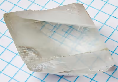
The propagation (as well as reflection coefficient) of the ordinary ray is simply described by no as if there were no birefringence involved. The extraordinary ray, as its name suggests, propagates unlike any wave in an isotropic optical material. Its refraction (and reflection) at a surface can be understood using the effective refractive index (a value in between no and ne). Its power flow (given by the Poynting vector) is not exactly in the direction of the wave vector. This causes an additional shift in that beam, even when launched at normal incidence, as is popularly observed using a crystal of calcite as photographed above. Rotating the calcite crystal will cause one of the two images, that of the extraordinary ray, to rotate slightly around that of the ordinary ray, which remains fixed.
When the light propagates either along or orthogonal to the optic axis, such a lateral shift (or double refracted image) does not occur. In the first case, both polarizations are perpendicular to the optic axis and see the same effective refractive index, so there is no extraordinary ray. In the second case the extraordinary ray propagates at a different phase velocity (corresponding to ne) but still has the power flow in the direction of the wave vector. A crystal with its optic axis parallel to the optical surface, may be used to create a waveplate, in which there is no distortion of the image but an intentional modification of the state of polarization of the incident wave. For instance, a quarter-wave plate is commonly used to create circular polarization from a linearly polarized source.
Biaxial materials
The case of so-called biaxial crystals is substantially more complex. These are characterized by three refractive indices corresponding to three principal axes of the crystal. For most ray directions, both polarizations would be classified as extraordinary rays but with different effective refractive indices. Being extraordinary waves, the direction of power flow is not identical to the direction of the wave vector in either case.
The two refractive indices can be determined using the index ellipsoids for given directions of the polarization. Note that for biaxial crystals the index ellipsoid will not be an ellipsoid of revolution ("spheroid") but is described by three unequal principle refractive indices nα, nβ and nγ. Thus there is no axis around which a rotation leaves the optical properties invariant (as there is with uniaxial crystals whose index ellipsoid is a spheroid).
Although there is no axis of symmetry, there are two optical axes or binormals which are defined as directions along which light may propagate without birefringence, i.e., directions along which the wavelength is independent of polarization. For this reason, birefringent materials with three distinct refractive indices are called biaxial. Additionally, there are two distinct axes known as optical ray axes or biradials along which the group velocity of the light is independent of polarization.
Double refraction
When an arbitrary beam of light strikes the surface of a birefringent material at non-normal incidence, the polarization component normal to the optic axis (ordinary ray) and the other linear polarization (extraordinary ray) will be refracted toward somewhat different paths. Natural light, so-called unpolarized light, consists of equal amounts of energy in any two orthogonal polarizations. Even linearly polarized light has some energy in both polarizations, unless aligned along one of the two axes of birefringence. According to Snell's law of refraction, the two angles of refraction are governed by the effective refractive index of each of these two polarizations. This is clearly seen, for instance, in the Wollaston prism which separates incoming light into two linear polarizations using prisms composed of a birefringent material such as calcite.
The different angles of refraction for the two polarization components are shown in the figure at the top of this page, with the optic axis along the surface (and perpendicular to the plane of incidence), so that the angle of refraction is different for the p polarization (the "ordinary ray" in this case, having its electric vector perpendicular to the optic axis) and the s polarization (the "extraordinary ray" in this case, whose electric field polarization includes a component in the direction of the optic axis). A distinct form of double refraction occurs, even with normal incidence, in cases where the optic axis is not along the refracting surface (nor exactly normal to it); in this case, the dielectric polarization of the birefringent material is not exactly in the direction of the wave's electric field for the extraordinary ray. The direction of power flow (given by the Poynting vector) for this inhomogenous wave is at a finite angle from the direction of the wave vector resulting in an additional separation between these beams. So even in the case of normal incidence, where one would compute the angle of refraction as zero (according to Snell's law, regardless of the effective index of refraction), the energy of the extraordinary ray is propagated at an angle. If exiting the crystal through a face parallel to the incoming face, the direction of both rays will be restored, but leaving a shift between the two beams. This is commonly observed using a piece of calcite cut along its natural cleavage, placed above a paper with writing, as in the above photograph. Hence, waveplates specifically have their optic axis along the surface of the plate, so that with (approximately) normal incidence there will be no shift in the image from light of either polarization, simply a relative phase shift between the two light waves.
Sign in to keep reading
6 more chapters are free with a Lably account.
Terminology
Much of the work involving polarization preceded the understanding of light as a transverse electromagnetic wave, and this has affected some terminology in use. Isotropic materials have symmetry in all directions and the refractive index is the same for any polarization direction. An anisotropic material is called "birefringent" because it will generally refract a single incoming ray in two directions, which we now understand correspond to the two different polarizations. This is true of either a uniaxial or biaxial material.
In a uniaxial material, one ray behaves according to the normal law of refraction (corresponding to the ordinary refractive index), so an incoming ray at normal incidence remains normal to the refracting surface. As explained above, the other polarization can deviate from normal incidence, which cannot be described using the law of refraction. This thus became known as the extraordinary ray. The terms "ordinary" and "extraordinary" are still applied to the polarization components perpendicular to and not perpendicular to the optic axis respectively, even in cases where no double refraction is involved.
A material is termed uniaxial when it has a single direction of symmetry in its optical behavior, which we term the optic axis. It also happens to be the axis of symmetry of the index ellipsoid (a spheroid in this case). The index ellipsoid could still be described according to the refractive indices, nα, nβ and nγ, along three coordinate axes; in this case two are equal. So if nα = nβ corresponding to the x and y axes, then the extraordinary index is nγ corresponding to the z axis, which is also called the optic axis in this case.
Materials in which all three refractive indices are different are termed biaxial and the origin of this term is more complicated and frequently misunderstood. In a uniaxial crystal, different polarization components of a beam will travel at different phase velocities, except for rays in the direction of what we call the optic axis. Thus the optic axis has the particular property that rays in that direction do not exhibit birefringence, with all polarizations in such a beam experiencing the same index of refraction. It is very different when the three principal refractive indices are all different; then an incoming ray in any of those principal directions will still encounter two different refractive indices. But it turns out that there are two special directions (at an angle to all of the three axes) where the refractive indices for different polarizations are again equal. For this reason, these crystals were designated as biaxial, with the two "axes" in this case referring to ray directions in which propagation does not experience birefringence.
Fast and slow rays
In a birefringent material, a wave consists of two polarization components which generally are governed by different effective refractive indices. The so-called slow ray is the component for which the material has the higher effective refractive index (slower phase velocity), while the fast ray is the one with a lower effective refractive index. When a beam is incident on such a material from air (or any material with a lower refractive index), the slow ray is thus refracted more towards the normal than the fast ray. In the example figure at top of this page, it can be seen that refracted ray with s polarization (with its electric vibration along the direction of the optic axis, thus called the extraordinary ray) is the slow ray in scenario 1.
Using a thin slab of that material at normal incidence, one would implement a waveplate. In this case, there is essentially no spatial separation between the polarizations, the phase of the wave in the parallel polarization (the slow ray) will be retarded with respect to the perpendicular polarization. These directions are thus known as the slow axis and fast axis of the waveplate.
Positive or negative
Uniaxial birefringence is classified as positive when the extraordinary index of refraction ne is greater than the ordinary index no. Negative birefringence means that Δn = ne − no is less than zero. In other words, the polarization of the fast (or slow) wave is perpendicular to the optic axis when the birefringence of the crystal is positive (or negative, respectively). In the case of biaxial crystals, all three of the principal axes have different refractive indices, so this designation does not apply. But for any defined ray direction one can just as well designate the fast and slow ray polarizations.
Sources of optical birefringence
While the best known source of birefringence is the entrance of light into an anisotropic crystal, it can result in otherwise optically isotropic materials in a few ways:
- Stress birefringence results when a normally isotropic solid is stressed and deformed (i.e., stretched or bent) causing a loss of physical isotropy and consequently a loss of isotropy in the material's permittivity tensor;
- Form birefringence, whereby structure elements such as rods, having one refractive index, are suspended in a medium with a different refractive index. When the lattice spacing is much smaller than a wavelength, such a structure is described as a metamaterial;
- By the Pockels or Kerr effect, whereby an applied electric field induces birefringence due to nonlinear optics;
- By the self or forced alignment into thin films of amphiphilic molecules such as lipids, some surfactants or liquid crystals;
- Circular birefringence takes place generally not in materials which are anisotropic but rather ones which are chiral. This can include liquids where there is an enantiomeric excess of a chiral molecule, that is, one that has stereo isomers;
- By the Faraday effect, where a longitudinal magnetic field causes some materials to become circularly birefringent (having slightly different indices of refraction for left- and right-handed circular polarizations), similar to optical activity while the field is applied.
Common birefringent materials
The best characterized birefringent materials are crystals. Due to their specific crystal structures their refractive indices are well defined. Depending on the symmetry of a crystal structure (as determined by one of the 32 possible crystallographic point groups), crystals in that group may be forced to be isotropic (not birefringent), to have uniaxial symmetry, or neither in which case it is a biaxial crystal. The crystal structures permitting uniaxial and biaxial birefringence are noted in the two tables, below, listing the two or three principal refractive indices (at wavelength 590 nm) of some better-known crystals.
In addition to induced birefringence while under stress, many plastics obtain permanent birefringence during manufacture due to stresses which are "frozen in" due to mechanical forces present when the plastic is molded or extruded. For example, ordinary cellophane is birefringent. Polarizers are routinely used to detect stress, either applied or frozen-in, in plastics such as polystyrene and polycarbonate.
Cotton fiber is birefringent because of high levels of cellulosic material in the fibre's secondary cell wall which is directionally aligned with the cotton fibers.
Polarized light microscopy is commonly used in biological tissue, as many biological materials are linearly or circularly birefringent. Collagen, found in cartilage, tendon, bone, corneas, and several other areas in the body, is birefringent and commonly studied with polarized light microscopy. Some proteins are also birefringent, exhibiting form birefringence.
Inevitable manufacturing imperfections in optical fiber leads to birefringence, which is one cause of pulse broadening in fiber-optic communications. Such imperfections can be geometrical (lack of circular symmetry), or due to unequal lateral stress applied to the optical fibre. Birefringence is intentionally introduced (for instance, by making the cross-section elliptical) in order to produce polarization-maintaining optical fibers. Birefringence can be induced (or corrected) in optical fibers through bending them which causes anisotropy in form and stress given the axis around which it is bent and radius of curvature.
In addition to anisotropy in the electric polarizability, anisotropy in the magnetic permeability could be a source of birefringence. At optical frequencies, there is no measurable magnetic polarizability (μ = μ0) of natural materials, so this is not an actual source of birefringence.
Measurement
Birefringence and other polarization-based optical effects (such as optical rotation and linear or circular dichroism) can be observed by measuring any change in the polarization of light passing through the material. These measurements are known as polarimetry. Polarized light microscopes, which contain two polarizers that are at 90° to each other on either side of the sample, are used to visualize birefringence, since light that has not been affected by birefringence remains in a polarization that is totally rejected by the second polarizer ("analyzer"). The addition of quarter-wave plates permits examination using circularly polarized light. Determination of the change in polarization state using such an apparatus is the basis of ellipsometry, by which the optical properties of specular surfaces can be gauged through reflection.
Birefringence measurements have been made with phase-modulated systems for examining the transient flow behaviour of fluids. Birefringence of lipid bilayers can be measured using dual-polarization interferometry. This provides a measure of the degree of order within these fluid layers and how this order is disrupted when the layer interacts with other biomolecules.
For the 3D measurement of birefringence, a technique based on holographic tomography can be used.
Applications
Optical devices
Birefringence is used in many optical devices. Liquid-crystal displays, the most common sort of flat-panel display, cause their pixels to become lighter or darker through rotation of the polarization (circular birefringence) of linearly polarized light as viewed through a sheet polarizer at the screen's surface. Similarly, light modulators modulate the intensity of light through electrically induced birefringence of polarized light followed by a polarizer. The Lyot filter is a specialized narrowband spectral filter employing the wavelength dependence of birefringence. Waveplates are thin birefringent sheets widely used in certain optical equipment for modifying the polarization state of light passing through it.
To manufacture polarizers with high transmittance, birefringent crystals are used in devices such as the Glan–Thompson prism, Glan–Taylor prism and other variants. Layered birefringent polymer sheets can also be used for this purpose.
Birefringence also plays an important role in second-harmonic generation and other nonlinear optical processes. The crystals used for these purposes are almost always birefringent. By adjusting the angle of incidence, the effective refractive index of the extraordinary ray can be tuned in order to achieve phase matching, which is required for the efficient operation of these devices.
Medicine
Birefringence is utilized in medical diagnostics. One powerful accessory used with optical microscopes is a pair of crossed polarizing filters. Light from the source is polarized in the x direction after passing through the first polarizer, but above the specimen is a polarizer (a so-called analyzer) oriented in the y direction. Therefore, no light from the source will be accepted by the analyzer, and the field will appear dark. Areas of the sample possessing birefringence will generally couple some of the x-polarized light into the y polarization; these areas will then appear bright against the dark background. Modifications to this basic principle can differentiate between positive and negative birefringence.
For instance, needle aspiration of fluid from a gouty joint will reveal negatively birefringent monosodium urate crystals. Calcium pyrophosphate crystals, in contrast, show weak positive birefringence. Urate crystals appear yellow, and calcium pyrophosphate crystals appear blue when their long axes are aligned parallel to that of a red compensator filter, or a crystal of known birefringence is added to the sample for comparison.
The birefringence of tissue inside a living human thigh was measured using polarization-sensitive optical coherence tomography at 1310 nm and a single mode fiber in a needle. Skeletal muscle birefringence was Δn = 1.79 × 10⁻³ ± 0.18×10⁻³, adipose Δn = 0.07 × 10⁻³ ± 0.50 × 10⁻³, superficial aponeurosis Δn = 5.08 × 10⁻³ ± 0.73 × 10⁻³ and interstitial tissue Δn = 0.65 × 10⁻³ ±0.39 × 10⁻³. These measurements may be important for the development of a less invasive method to diagnose Duchenne muscular dystrophy.
Birefringence can be observed in amyloid plaques such as are found in the brains of Alzheimer's patients when stained with a dye such as Congo Red. Modified proteins such as immunoglobulin light chains abnormally accumulate between cells, forming fibrils. Multiple folds of these fibers line up and take on a beta-pleated sheet conformation. Congo red dye intercalates between the folds and, when observed under polarized light, causes birefringence.
In ophthalmology, binocular retinal birefringence screening of the Henle fibers (photoreceptor axons that go radially outward from the fovea) provides a reliable detection of strabismus and possibly also of anisometropic amblyopia. In healthy subjects, the maximum retardation induced by the Henle fiber layer is approximately 22 degrees at 840 nm. Furthermore, scanning laser polarimetry uses the birefringence of the optic nerve fiber layer to indirectly quantify its thickness, which is of use in the assessment and monitoring of glaucoma. Polarization-sensitive optical coherence tomography measurements obtained from healthy human subjects have demonstrated a change in birefringence of the retinal nerve fiber layer as a function of location around the optic nerve head. The same technology was recently applied in the living human retina to quantify the polarization properties of vessel walls near the optic nerve. While retinal vessel walls become thicker and less birefringent in patients who suffer from hypertension, hinting at a decrease in vessel wall condition, the vessel walls of diabetic patients do not experience a change in thickness, but do see an increase in birefringence, presumably due to fibrosis or inflammation.
Birefringence characteristics in sperm heads allow the selection of spermatozoa for intracytoplasmic sperm injection. Likewise, zona imaging uses birefringence on oocytes to select the ones with highest chances of successful pregnancy. Birefringence of particles biopsied from pulmonary nodules indicates silicosis.
Dermatologists use dermatoscopes to view skin lesions. Dermoscopes use polarized light, allowing the user to view crystalline structures corresponding to dermal collagen in the skin. These structures may appear as shiny white lines or rosette shapes and are only visible under polarized dermoscopy.
Stress-induced birefringence
Isotropic solids do not exhibit birefringence. When they are under mechanical stress, birefringence results due to change of refractive index caused by stress. The stress can be applied externally or is "frozen in" after a birefringent plasticware is cooled after it is manufactured using injection molding. When such a sample is placed between two crossed polarizers, colour patterns can be observed, because polarization of a light ray is rotated after passing through a birefringent material and the amount of rotation is dependent on wavelength. The experimental method called photoelasticity used for analyzing stress distribution in solids is based on the same principle. There has been recent research on using stress-induced birefringence in a glass plate to generate an optical vortex and full Poincaré beams (optical beams that have every possible polarization state across a cross-section).
Other cases of birefringence
Birefringence is observed in anisotropic elastic materials. In these materials, the two polarizations split according to their effective refractive indices, which are also sensitive to stress.
The study of birefringence in shear waves traveling through the solid Earth (the Earth's liquid core does not support shear waves) is widely used in seismology.
Birefringence is widely used in mineralogy to identify rocks, minerals, and gemstones.
Theory
In an isotropic medium (including free space) the so-called electric displacement (D) is just proportional to the electric field (E) according to D = ɛE where the material's permittivity ε is just a scalar (and equal to n2ε0 where n is the index of refraction). In an anisotropic material exhibiting birefringence, the relationship between D and E must now be described using a tensor equation:
where ε is now a 3 × 3 permittivity tensor. We assume linearity and no magnetic permeability in the medium: μ = μ0. The electric field of a plane wave of angular frequency ω can be written in the general form:
where r is the position vector, t is time, and E0 is a vector describing the electric field at r = 0, t = 0. Then we shall find the possible wave vectors k. By combining Maxwell's equations for ∇ × E and ∇ × H, we can eliminate H = 1/μ0B to obtain:
With no free charges, Maxwell's equation for the divergence of D vanishes:
We can apply the vector identity ∇ × (∇ × A) = ∇(∇ ⋅ A) − ∇2A to the left hand side of eq. 3a, and use the spatial dependence in which each differentiation in x (for instance) results in multiplication by ikx to find:
The right hand side of eq. 3a can be expressed in terms of E through application of the permittivity tensor ε and noting that differentiation in time results in multiplication by −iω, eq. 3a then becomes:
Applying the differentiation rule to eq. 3b we find:
Eq. 4b indicates that D is orthogonal to the direction of the wavevector k, even though that is no longer generally true for E as would be the case in an isotropic medium. Eq. 4b will not be needed for the further steps in the following derivation.
Finding the allowed values of k for a given ω is easiest done by using Cartesian coordinates with the x, y and z axes chosen in the directions of the symmetry axes of the crystal (or simply choosing z in the direction of the optic axis of a uniaxial crystal), resulting in a diagonal matrix for the permittivity tensor ε:
where the diagonal values are squares of the refractive indices for polarizations along the three principal axes x, y and z. With ε in this form, and substituting in the speed of light c using c2 = 1/μ0ε0, the x component of the vector equation eq. 4a becomes
where Ex, Ey, Ez are the components of E (at any given position in space and time) and kx, ky, kz are the components of k. Rearranging, we can write (and similarly for the y and z components of eq. 4a)
This is a set of linear equations in Ex, Ey, Ez, so it can have a nontrivial solution (that is, one other than E = 0) as long as the following determinant is zero:
Evaluating the determinant of eq. 6, and rearranging the terms according to the powers of , the constant terms cancel. After eliminating the common factor from the remaining terms, we obtain
In the case of a uniaxial material, choosing the optic axis to be in the z direction so that nx = ny = no and nz = ne, this expression can be factored into
Setting either of the factors in eq. 8 to zero will define an ellipsoidal surface in the space of wavevectors k that are allowed for a given ω. The first factor being zero defines a sphere; this is the solution for so-called ordinary rays, in which the effective refractive index is exactly no regardless of the direction of k. The second defines a spheroid symmetric about the z axis. This solution corresponds to the so-called extraordinary rays in which the effective refractive index is in between no and ne, depending on the direction of k. Therefore, for any arbitrary direction of propagation (other than in the direction of the optic axis), two distinct wavevectors k are allowed corresponding to the polarizations of the ordinary and extraordinary rays.
For a biaxial material a similar but more complicated condition on the two waves can be described; the locus of allowed k vectors (the wavevector surface) is a 4th-degree two-sheeted surface, so that in a given direction there are generally two permitted k vectors (and their opposites). By inspection one can see that eq. 6 is generally satisfied for two positive values of ω. Or, for a specified optical frequency ω and direction normal to the wavefronts k/|k|, it is satisfied for two wavenumbers (or propagation constants) |k| (and thus effective refractive indices) corresponding to the propagation of two linear polarizations in that direction.
When those two propagation constants are equal then the effective refractive index is independent of polarization, and there is consequently no birefringence encountered by a wave traveling in that particular direction. For a uniaxial crystal, this is the optic axis, the ±z direction according to the above construction. But when all three refractive indices (or permittivities), nx, ny and nz are distinct, it can be shown that there are exactly two such directions, where the two sheets of the wave-vector surface touch; these directions are not at all obvious and do not lie along any of the three principal axes (x, y, z according to the above convention). Historically that accounts for the use of the term "biaxial" for such crystals, as the existence of exactly two such special directions (considered "axes") was discovered well before polarization and birefringence were understood physically. These two special directions are generally not of particular interest; biaxial crystals are rather specified by their three refractive indices corresponding to the three axes of symmetry.
A general state of polarization launched into the medium can always be decomposed into two waves, one in each of those two polarizations, which will then propagate with different wavenumbers |k|. Applying the different phase of propagation to those two waves over a specified propagation distance will result in a generally different net polarization state at that point; this is the principle of the waveplate for instance. With a waveplate, there is no spatial displacement between the two rays as their k vectors are still in the same direction. That is true when each of the two polarizations is either normal to the optic axis (the ordinary ray) or parallel to it (the extraordinary ray).
In the more general case, there is a difference not only in the magnitude but the direction of the two rays. For instance, the photograph through a calcite crystal (top of page) shows a shifted image in the two polarizations; this is due to the optic axis being neither parallel nor normal to the crystal surface. And even when the optic axis is parallel to the surface, this will occur for waves launched at non-normal incidence (as depicted in the explanatory figure). In these cases the two k vectors can be found by solving eq. 6 constrained by the boundary condition which requires that the components of the two transmitted waves' k vectors, and the k vector of the incident wave, as projected onto the surface of the interface, must all be identical. For a uniaxial crystal it will be found that there is not a spatial shift for the ordinary ray (hence its name) which will refract as if the material were non-birefringent with an index the same as the two axes which are not the optic axis. For a biaxial crystal neither ray is deemed "ordinary" nor would generally be refracted according to a refractive index equal to one of the principal axes.