

Electron diffraction
Bending of electron beams due to electrostatic interactions with matter
- 37 min read
- 4 chapters

Related on Lably
Through Atom, Coulomb's law and Electron microscope
This article provides an overview of electron diffraction and electron diffraction patterns, collectively referred to by the generic name electron diffraction. This includes aspects of how in a general way electrons can act as waves, and diffract and interact with matter. It also involves the extensive history behind modern electron diffraction, how the combination of developments in the 19th century in understanding and controlling electrons in vacuum and the early 20th century developments with electron waves were combined with early instruments, giving birth to electron microscopy and diffraction in 1920–1935. While this was the birth, there have been a large number of further developments since then.
There are many types and techniques of electron diffraction. The most common approach is where the electrons transmit through a thin sample, from 1 nm to 100 nm (10 to 1000 atoms thick), where the results depend upon how the atoms are arranged in the material, for instance a single crystal, many crystals or different types of solids. Other cases such as larger repeats, no periodicity or disorder have their own characteristic patterns. There are many different ways of collecting diffraction information, from parallel illumination to a converging beam of electrons or where the beam is rotated or scanned across the sample which produce information that is often easier to interpret. There are also many other types of instruments. For instance, in a scanning electron microscope (SEM), electron backscatter diffraction can be used to determine crystal orientation across the sample. Electron diffraction patterns can also be used to characterize molecules using gas electron diffraction, liquids, surfaces using lower energy electrons, a technique called LEED, and by reflecting electrons off surfaces, a technique called RHEED.
There are also many levels of analysis of electron diffraction, including:
- The simplest approximation using the de Broglie wavelength for electrons, where only the geometry is considered and often Bragg's law is invoked. This approach only considers the electrons far from the sample, a far-field or Fraunhofer approach.
- The first level of more accuracy where it is approximated that the electrons are only scattered once, which is called kinematical diffraction and is also a far-field or Fraunhofer approach.
- More complete and accurate explanations where multiple scattering is included, what is called dynamical diffraction (e.g. refs). These involve more general analyses using relativistically corrected Schrödinger equation methods, and track the electrons through the sample, being accurate both near and far from the sample (both Fresnel and Fraunhofer diffraction).
Although similar to x-ray and neutron diffraction, where the simplest approximations are quite accurate, simple models for electron diffraction only provide the geometry of the intensities in a diffraction pattern. Dynamical diffraction approaches are needed to calculate more accurate intensities and the positions of diffraction spots.
A primer on electron diffraction
All matter can be thought of as matter waves, from small particles such as electrons up to macroscopic objects – although it is impossible to measure any of the "wave-like" behavior of macroscopic objects. Waves can move around objects and create interference patterns, and a classic example is the Young's two-slit experiment shown in Figure 2, where a wave impinges upon two slits in the first of the two images (blue waves). After going through the slits there are directions where the wave is stronger, ones where it is weaker – the wave has been diffracted. If instead of two slits there are a number of small points then similar phenomena can occur as shown in the second image where the wave (red and blue) is coming in from the bottom right corner. This is comparable to diffraction of an electron wave where the small dots would be atoms in a small crystal, see also note. Note the strong dependence on the relative orientation of the crystal and the incoming wave.
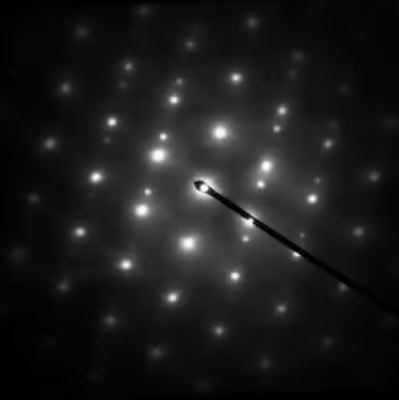
Close to an aperture or atoms, often called the "sample", the electron wave would be described in terms of near field or Fresnel diffraction. This has relevance for imaging within electron microscopes, whereas electron diffraction patterns are measured far from the sample, which is described as far-field or Fraunhofer diffraction. A map of the directions of the electron waves leaving the sample will show high intensity (white) for favored directions, such as the three prominent ones in the Young's two-slit experiment of Figure 2, while the other directions will be low intensity (dark). Often there will be an array of spots (preferred directions) as in Figure 1 and the other figures shown later.
Sign in to keep reading
3 more chapters are free with a Lably account.
History
The historical background is divided into several subsections. The first is the general background to electrons in vacuum and the technological developments that led to cathode-ray tubes as well as vacuum tubes that dominated early television and electronics; the second is how these led to the development of electron microscopes; the last is work on the nature of electron beams and the fundamentals of how electrons behave, a key component of quantum mechanics and the explanation of electron diffraction.
Electrons in vacuum
Experiments involving electron beams occurred long before the discovery of the electron; ēlektron (ἤλεκτρον) is the Greek word for amber, which is connected to the recording of electrostatic charging by Thales of Miletus around 585 BCE, and possibly others even earlier.
In 1650, Otto von Guericke invented the vacuum pump allowing for the study of the effects of high voltage electricity passing through rarefied air. In 1838, Michael Faraday applied a high voltage between two metal electrodes at either end of a glass tube that had been partially evacuated of air, and noticed a strange light arc with its beginning at the cathode (negative electrode) and its end at the anode (positive electrode). Building on this, in the 1850s, Heinrich Geissler was able to achieve a pressure of around 10−3 atmospheres, inventing what became known as Geissler tubes. Using these tubes, while studying electrical conductivity in rarefied gases in 1859, Julius Plücker observed that the radiation emitted from the negatively charged cathode caused phosphorescent light to appear on the tube wall near it, and the region of the phosphorescent light could be moved by application of a magnetic field.
In 1869, Plücker's student Johann Wilhelm Hittorf found that a solid body placed between the cathode and the phosphorescence would cast a shadow on the tube wall, e.g. Figure 3. Hittorf inferred that there are straight rays emitted from the cathode and that the phosphorescence was caused by the rays striking the tube walls. In 1876 Eugen Goldstein showed that the rays were emitted perpendicular to the cathode surface, which differentiated them from the incandescent light. Eugen Goldstein dubbed them cathode rays. By the 1870s William Crookes and others were able to evacuate glass tubes below 10−6 atmospheres, and observed that the glow in the tube disappeared when the pressure was reduced but the glass behind the anode began to glow. Crookes was also able to show that the particles in the cathode rays were negatively charged and could be deflected by an electromagnetic field.
In 1897, Joseph Thomson measured the mass of these cathode rays, proving they were made of particles. These particles, however, were 1800 times lighter than the lightest particle known at that time – a hydrogen atom. These were originally called corpuscles and later named electrons by George Johnstone Stoney.
The control of electron beams that this work led to resulted in significant technology advances in electronic amplifiers and television displays.
Waves, diffraction and quantum mechanics
Independent of the developments for electrons in vacuum, at about the same time the components of quantum mechanics were being assembled. In 1924 Louis de Broglie in his PhD thesis Recherches sur la théorie des quanta introduced his theory of electron waves. He suggested that an electron around a nucleus could be thought of as standing waves, and that electrons and all matter could be considered as waves. He merged the idea of thinking about them as particles (or corpuscles), and of thinking of them as waves. He proposed that particles are bundles of waves (wave packets) that move with a group velocity and have an effective mass, see for instance Figure 4. Both of these depend upon the energy, which in turn connects to the wavevector and the relativistic formulation of Albert Einstein a few years before.
This rapidly became part of what was called by Erwin Schrödinger undulatory mechanics, now called the Schrödinger equation or wave mechanics. As stated by Louis de Broglie on September 8, 1927, in the preface to the German translation of his theses (in turn translated into English):
M. Einstein from the beginning has supported my thesis, but it was M. E. Schrödinger who developed the propagation equations of a new theory and who in searching for its solutions has established what has become known as "Wave Mechanics".
The Schrödinger equation combines the kinetic energy of waves and the potential energy due to, for electrons, the Coulomb potential. He was able to explain earlier work such as the quantization of the energy of electrons around atoms in the Bohr model, as well as many other phenomena. Electron waves as hypothesized by de Broglie were automatically part of the solutions to his equation, see also introduction to quantum mechanics and matter waves.
Both the wave nature and the undulatory mechanics approach were experimentally confirmed for electron beams by experiments from two groups performed independently, the first the Davisson–Germer experiment, the other by George Paget Thomson and Alexander Reid; see note for more discussion. Alexander Reid, who was Thomson's graduate student, performed the first experiments, but he died soon after in a motorcycle accident and is rarely mentioned. These experiments were rapidly followed by the first non-relativistic diffraction model for electrons by Hans Bethe based upon the Schrödinger equation, which is very close to how electron diffraction is now described. Significantly, Clinton Davisson and Lester Germer noticed that their results could not be interpreted using a Bragg's law approach as the positions were systematically different; the approach of Hans Bethe which includes the refraction due to the average potential yielded more accurate results. These advances in understanding of electron wave mechanics were important for many developments of electron-based analytical techniques such as Seishi Kikuchi's observations of lines due to combined elastic and inelastic scattering, gas electron diffraction developed by Herman Mark and Raymond Weil, diffraction in liquids by Louis Maxwell, and the first electron microscopes developed by Max Knoll and Ernst Ruska.
Electron microscopes and early electron diffraction
In order to have a practical microscope or diffractometer, just having an electron beam was not enough, it needed to be controlled. Many developments laid the groundwork of electron optics; see the paper by Chester J. Calbick for an overview of the early work. One significant step was the work of Heinrich Hertz in 1883 who made a cathode-ray tube with electrostatic and magnetic deflection, demonstrating manipulation of the direction of an electron beam. Others were focusing of electrons by an axial magnetic field by Emil Wiechert in 1899, improved oxide-coated cathodes which produced more electrons by Arthur Wehnelt in 1905 and the development of the electromagnetic lens in 1926 by Hans Busch.
Building an electron microscope involves combining these elements, similar to an optical microscope but with magnetic or electrostatic lenses instead of glass ones. To this day the issue of who invented the transmission electron microscope is controversial, as discussed by Thomas Mulvey and more recently by Yaping Tao. Extensive additional information can be found in the articles by Martin Freundlich, Reinhold Rüdenberg and Mulvey.
One effort was university based. In 1928, at the Technische Hochschule in Charlottenburg (now Technische Universität Berlin), Adolf Matthias (Professor of High Voltage Technology and Electrical Installations) appointed Max Knoll to lead a team of researchers to advance research on electron beams and cathode-ray oscilloscopes. The team consisted of several PhD students including Ernst Ruska. In 1931, Max Knoll and Ernst Ruska successfully generated magnified images of mesh grids placed over an anode aperture. The device, a replicate of which is shown in Figure 5, used two magnetic lenses to achieve higher magnifications, the first electron microscope. (Max Knoll died in 1969, so did not receive a share of the Nobel Prize in Physics in 1986.)
Apparently independent of this effort was work at Siemens-Schuckert by Reinhold Rudenberg. According to patent law (U.S. Patent No. 2058914 and 2070318, both filed in 1932), he is the inventor of the electron microscope, but it is not clear when he had a working instrument. He stated in a very brief article in 1932 that Siemens had been working on this for some years before the patents were filed in 1932, so his effort was parallel to the university effort. He died in 1961, so similar to Max Knoll, was not eligible for a share of the Nobel Prize.
These instruments could produce magnified images, but were not particularly useful for electron diffraction; indeed, the wave nature of electrons was not exploited during the development. Key for electron diffraction in microscopes was the advance in 1936 where Hans Boersch showed that they could be used as micro-diffraction cameras with an aperture—the birth of selected area electron diffraction.
Less controversial was the development of LEED—the early experiments of Davisson and Germer used this approach. As early as 1929 Germer investigated gas adsorption, and in 1932 Harrison E. Farnsworth probed single crystals of copper and silver. However, the vacuum systems available at that time were not good enough to properly control the surfaces, and it took almost forty years before these became available. Similarly, it was not until about 1965 that Peter B. Sewell and M. Cohen demonstrated the power of RHEED in a system with a very well controlled vacuum.
Subsequent developments in methods and modelling
Despite early successes such as the determination of the positions of hydrogen atoms in NH4Cl crystals by W. E. Laschkarew and I. D. Usykin in 1933, boric acid by John M. Cowley in 1953 and orthoboric acid by William Houlder Zachariasen in 1954, electron diffraction for many years was a qualitative technique used to check samples within electron microscopes. John M Cowley explains in a 1968 paper:
Thus was founded the belief, amounting in some cases almost to an article of faith, and persisting even to the present day, that it is impossible to interpret the intensities of electron diffraction patterns to gain structural information.
This has changed, in transmission, reflection and for low energies. Some of the key developments (some of which are also described later) from the early days to 2023 have been:
- Fast numerical methods based upon the Cowley–Moodie multislice algorithm, which only became possible once the fast Fourier transform (FFT) method was developed. With these and other numerical methods Fourier transforms are fast, and it became possible to calculate accurate, dynamical diffraction in seconds to minutes with laptops using widely available multislice programs.
- Developments in the convergent-beam electron diffraction approach. Building on the original work of Walther Kossel and Gottfried Möllenstedt in 1939, it was extended by Peter Goodman and Gunter Lehmpfuhl, then mainly by the groups of John Steeds and Michiyoshi Tanaka who showed how to determine point groups and space groups. It can also be used for higher-level refinements of the electron density; for a brief history see CBED history. In many cases this is the best method to determine symmetry.
- The development of new approaches to reduce dynamical effects such as precession electron diffraction and three-dimensional diffraction methods. Averaging over different directions has, empirically, been found to significantly reduce dynamical diffraction effects, e.g., see PED history for further details. Not only is it easier to identify known structures with this approach, it can also be used to solve unknown structures in some cases – see precession electron diffraction for further information.
- The development of experimental methods exploiting ultra-high vacuum technologies (e.g. the approach described by Daniel J. Alpert in 1953) to better control surfaces, making LEED and RHEED more reliable and reproducible techniques. In the early days the surfaces were not well controlled; with these technologies they can both be cleaned and remain clean for hours to days, a key component of surface science.
- Fast and accurate methods to calculate intensities for LEED so it could be used to determine atomic positions, for instance references. These have been extensively exploited to determine the structure of many surfaces, and the arrangement of foreign atoms on surfaces.
- Methods to simulate the intensities in RHEED, so it can be used semi-quantitatively to understand surfaces during growth and thereby to control the resulting materials.
- The development of advanced detectors for transmission electron microscopy such as charge-coupled device and direct electron detectors, which improve the accuracy and reliability of intensity measurements. These have efficiencies and accuracies that can be a thousand or more times that of the photographic film used in the earliest experiments, with the information available in real time rather than requiring photographic processing after the experiment.
Core elements of electron diffraction
Plane waves, wavevectors and reciprocal lattice
What is seen in an electron diffraction pattern depends upon the sample and also the energy of the electrons. The electrons need to be considered as waves, which involves describing the electron via a wavefunction, written in crystallographic notation (see notes and) as:for a position . This is a quantum mechanics description; one cannot use a classical approach. The vector is called the wavevector, has units of inverse nanometers, and the form above is called a plane wave as the term inside the exponential is constant on the surface of a plane. The vector is what is used when drawing ray diagrams, and in vacuum is parallel to the direction or, better, group velocity or probability current of the plane wave. For most cases the electrons are travelling at a respectable fraction of the speed of light, so rigorously need to be considered using relativistic quantum mechanics via the Dirac equation, which as spin does not normally matter can be reduced to the Klein–Gordon equation. Fortunately one can side-step many complications and use a non-relativistic approach based around the Schrödinger equation. Following Kunio Fujiwara and Archibald Howie, the relationship between the total energy of the electrons and the wavevector is written as:withwhere is the Planck constant, is a relativistic effective mass used to cancel out the relativistic terms for electrons of energy with the speed of light and the rest mass of the electron. The concept of effective mass occurs throughout physics (see for instance Ashcroft and Mermin), and comes up in the behavior of quasiparticles. A common one is the electron hole, which acts as if it is a particle with a positive charge and a mass similar to that of an electron, although it can be several times lighter or heavier. For electron diffraction the electrons behave as if they are non-relativistic particles of mass in terms of how they interact with the atoms.
The wavelength of the electrons in vacuum is from the above equationsand can range from about 0.1 nm, roughly the size of an atom, down to a thousandth of that. Typically the energy of the electrons is written in electronvolts (eV), the voltage used to accelerate the electrons; the actual energy of each electron is this voltage times the electron charge. For context, the typical energy of a chemical bond is a few eV; electron diffraction involves electrons up to 5000000 eV.
The magnitude of the interaction of the electrons with a material scales asWhile the wavevector increases as the energy increases, the change in the effective mass compensates this so even at the very high energies used in electron diffraction there are still significant interactions.
The high-energy electrons interact with the Coulomb potential, which for a crystal can be considered in terms of a Fourier series (see for instance Ashcroft and Mermin), that iswith a reciprocal lattice vector and the corresponding Fourier coefficient of the potential. The reciprocal lattice vector is often referred to in terms of Miller indices , a sum of the individual reciprocal lattice vectors with integers in the form:(Sometimes reciprocal lattice vectors are written as , , and see note.) The contribution from the needs to be combined with what is called the shape function (e.g.), which is the Fourier transform of the shape of the object. If, for instance, the object is small in one dimension then the shape function extends far in that direction in the Fourier transform—a reciprocal relationship.
Around each reciprocal lattice point one has this shape function. How much intensity there will be in the diffraction pattern depends upon the intersection of the Ewald sphere, that is energy conservation, and the shape function around each reciprocal lattice point—see Figure 6, 20 and 22. The vector from a reciprocal lattice point to the Ewald sphere is called the excitation error .
For transmission electron diffraction the samples used are thin, so most of the shape function is along the direction of the electron beam. For both LEED and RHEED the shape function is mainly normal to the surface of the sample. In LEED this results in (a simplification) back-reflection of the electrons leading to spots, see Figure 20 and 21 later, whereas in RHEED the electrons reflect off the surface at a small angle and typically yield diffraction patterns with streaks, see Figure 22 and 23 later. By comparison, with both x-ray and neutron diffraction the scattering is significantly weaker, so typically requires much larger crystals, in which case the shape function shrinks to just around the reciprocal lattice points, leading to simpler Bragg's law diffraction.
For all cases, when the reciprocal lattice points are close to the Ewald sphere (the excitation error is small) the intensity tends to be higher; when they are far away it tends to be smaller. The set of diffraction spots at right angles to the direction of the incident beam are called the zero-order Laue zone (ZOLZ) spots, as shown in Figure 6. One can also have intensities further out from reciprocal lattice points which are in a higher layer. The first of these is called the first order Laue zone (FOLZ); the series is called by the generic name higher order Laue zone (HOLZ).
The result is that the electron wave after it has been diffracted can be written as an integral over different plane waves:that is a sum of plane waves going in different directions, each with a complex amplitude . (This is a three dimensional integral, which is often written as rather than .) For a crystalline sample these wavevectors have to be of the same magnitude for elastic scattering (no change in energy), and are related to the incident direction by (see Figure 6) A diffraction pattern detects the intensitiesFor a crystal these will be near the reciprocal lattice points typically forming a two dimensional grid. Different samples and modes of diffraction give different results, as do different approximations for the amplitudes .
A typical electron diffraction pattern in TEM and LEED is a grid of high intensity spots (white) on a dark background, approximating a projection of the reciprocal lattice vectors, see Figure 1, 9, 10, 11, 14 and 21 later. There are also cases which will be mentioned later where diffraction patterns are not periodic, see Figure 15, have additional diffuse structure as in Figure 16, or have rings as in Figure 12, 13 and 24. With conical illumination as in CBED they can also be a grid of discs, see Figure 7, 9 and 18. RHEED is slightly different, see Figure 22, 23. If the excitation errors were zero for every reciprocal lattice vector, this grid would be at exactly the spacings of the reciprocal lattice vectors. This would be equivalent to a Bragg's law condition for all of them. In TEM the wavelength is small and this is close to correct, but not exact. In practice the deviation of the positions from a simple Bragg's law interpretation is often neglected, particularly if a column approximation is made (see below).
Kinematical diffraction
In Kinematical theory an approximation is made that the electrons are only scattered once. For transmission electron diffraction it is common to assume a constant thickness , and also what is called the Column Approximation (e.g. references and further reading). For a perfect crystal the intensity for each diffraction spot is then:where is the magnitude of the excitation error along z, the distance along the beam direction (z-axis by convention) from the diffraction spot to the Ewald sphere, and is the structure factor:the sum being over all the atoms in the unit cell with the form factors, the reciprocal lattice vector, is a simplified form of the Debye–Waller factor, and is the wavevector for the diffraction beam which is:for an incident wavevector of , as in Figure 6 and above. The excitation error comes in as the outgoing wavevector has to have the same modulus (i.e. energy) as the incoming wavevector . The intensity in transmission electron diffraction oscillates as a function of thickness, which can be confusing; there can similarly be intensity changes due to variations in orientation and also structural defects such as dislocations. If a diffraction spot is strong it could be because it has a larger structure factor, or it could be because the combination of thickness and excitation error is "right". Similarly the observed intensity can be small, even though the structure factor is large. This can complicate interpretation of the intensities. By comparison, these effects are much smaller in x-ray diffraction or neutron diffraction because they interact with matter far less and often Bragg's law is adequate.
This form is a reasonable first approximation which is qualitatively correct in many cases, but more accurate forms including multiple scattering (dynamical diffraction) of the electrons are needed to properly understand the intensities.
Dynamical diffraction
While kinematical diffraction is adequate to understand the geometry of the diffraction spots, it does not correctly give the intensities and has a number of other limitations. For a more complete approach one has to include multiple scattering of the electrons using methods that date back to the early work of Hans Bethe in 1928. These are based around solutions of the Schrödinger equation using the relativistic effective mass described earlier. Even at very high energies dynamical diffraction is needed as the relativistic mass and wavelength partially cancel, so the role of the potential is larger than might be thought.
The main components of current dynamical diffraction of electrons include:
- Taking into account the scattering back into the incident beam both from diffracted beams and between all others, not just single scattering from the incident beam to diffracted beams. This is important even for samples which are only a few atoms thick.
- Modelling at least semi-empirically the role of inelastic scattering by an imaginary component of the potential, also called an "optical potential". There is always inelastic scattering, and often it can have a major effect on both the background and sometimes the details, see Figure 7 and 18.
- Higher-order numerical approaches to calculate the intensities such as multislice, matrix methods which are called Bloch-wave approaches or muffin-tin approaches. With these diffraction spots which are not present in kinematical theory can be present, e.g.
- Contributions to the diffraction from elastic strain and crystallographic defects, and also what Jens Lindhard called the string potential.
- For transmission electron microscopes effects due to variations in the thickness of the sample and the normal to the surface.
- Both in the geometry of scattering and calculations, for both LEED and RHEED, effects due to the presence of surface steps, surface reconstructions and other atoms at the surface. Often these change the diffraction details significantly.
- For LEED, use more careful analyses of the potential because contributions from exchange terms can be important. Without these the calculations may not be accurate enough.
Kikuchi lines
Kikuchi lines, first observed by Seishi Kikuchi in 1928, are linear features created by electrons scattered both inelastically and elastically. As the electron beam interacts with matter, the electrons are diffracted via elastic scattering, and also scattered inelastically losing part of their energy. These occur simultaneously, and cannot be separated – according to the Copenhagen interpretation of quantum mechanics, only the probabilities of electrons at detectors can be measured. These electrons form Kikuchi lines which provide information on the orientation.
Kikuchi lines come in pairs forming Kikuchi bands, and are indexed in terms of the crystallographic planes they are connected to, with the angular width of the band equal to the magnitude of the corresponding diffraction vector . The position of Kikuchi bands is fixed with respect to each other and the orientation of the sample, but not against the diffraction spots or the direction of the incident electron beam. As the crystal is tilted, the bands move on the diffraction pattern. Since the position of Kikuchi bands is quite sensitive to crystal orientation, they can be used to fine-tune a zone-axis orientation or determine crystal orientation. They can also be used for navigation when changing the orientation between zone axes connected by some band, an example of such a map produced by combining many local sets of experimental Kikuchi patterns is in Figure 8; Kikuchi maps are available for many materials.
Types and techniques
In a transmission electron microscope
Electron diffraction in a TEM exploits controlled electron beams using electron optics. Different types of diffraction experiments, for instance Figure 9, provide information such as lattice constants, symmetries, and sometimes to solve an unknown crystal structure.
It is common to combine it with other methods, for instance images using selected diffraction beams, high-resolution images showing the atomic structure, chemical analysis through energy-dispersive x-ray spectroscopy, investigations of electronic structure and bonding through electron energy loss spectroscopy, and studies of the electrostatic potential through electron holography; this list is not exhaustive. Compared to x-ray crystallography, TEM analysis is significantly more localized and can be used to obtain information from tens of thousands of atoms to just a few or even single atoms.
Formation of a diffraction pattern
In TEM, the electron beam passes through a thin film of the material as illustrated in Figure 10. Before and after the sample the beam is manipulated by the electron optics including magnetic lenses, deflectors and apertures; these act on the electrons similar to how glass lenses focus and control light. Optical elements above the sample are used to control the incident beam which can range from a wide and parallel beam to one which is a converging cone and can be smaller than an atom, 0.1 nm. As it interacts with the sample, part of the beam is diffracted and part is transmitted without changing its direction. This occurs simultaneously as electrons are everywhere until they are detected (wavefunction collapse) according to the Copenhagen interpretation.
Below the sample, the beam is controlled by another set of magnetic lenses and apertures. Each set of initially parallel rays (a plane wave) is focused by the first lens (objective) to a point in the back focal plane of this lens, forming a spot on a detector; a map of these directions, often an array of spots, is the diffraction pattern. Alternatively the lenses can form a magnified image of the sample. Herein the focus is on collecting a diffraction pattern; for other information see the pages on TEM and scanning transmission electron microscopy.
Selected area electron diffraction
The simplest diffraction technique in TEM is selected area electron diffraction (SAED) where the incident beam is wide and close to parallel. An aperture is used to select a particular region of interest from which the diffraction is collected. These apertures are part of a thin foil of a heavy metal such as tungsten which has a number of small holes in it. This way diffraction information can be limited to, for instance, individual crystallites. Unfortunately the method is limited by the spherical aberration of the objective lens, so is only accurate for large grains with tens of thousands of atoms or more; for smaller regions a focused probe is needed.
If a parallel beam is used to acquire a diffraction pattern from a single-crystal, the result is similar to a two-dimensional projection of the crystal reciprocal lattice. From this one can determine interplanar distances and angles and in some cases crystal symmetry, particularly when the electron beam is down a major zone axis, see for instance the database by Jean-Paul Morniroli. However, projector lens aberrations such as barrel distortion as well as dynamical diffraction effects (e.g.) cannot be ignored. For instance, certain diffraction spots which are not present in x-ray diffraction can appear, for instance those due to Gjønnes-Moodie extinction conditions.
If the sample is tilted relative to the electron beam, different sets of crystallographic planes contribute to the pattern yielding different types of diffraction patterns, approximately different projections of the reciprocal lattice, see Figure 11. This can be used to determine the crystal orientation, which in turn can be used to set the orientation needed for a particular experiment. Furthermore, a series of diffraction patterns varying in tilt can be acquired and processed using a diffraction tomography approach. There are ways to combine this with direct methods algorithms using electrons and other methods such as charge flipping, or automated diffraction tomography to solve crystal structures.
Polycrystalline pattern
Diffraction patterns depend on whether the beam is diffracted by one single crystal or by a number of differently oriented crystallites, for instance in a polycrystalline material. If there are many contributing crystallites, the diffraction image is a superposition of individual crystal patterns, see Figure 12. With a large number of grains this superposition yields diffraction spots of all possible reciprocal lattice vectors. This results in a pattern of concentric rings as shown in Figure 12 and 13.
Textured materials yield a non-uniform distribution of intensity around the ring, which can be used to discriminate between nanocrystalline and amorphous phases. However, diffraction often cannot differentiate between very small grain polycrystalline materials and truly random order amorphous. Here high-resolution transmission electron microscopy and fluctuation electron microscopy can be more powerful, although this is still a topic of continuing development.
Multiple materials and double diffraction
In simple cases there is only one grain or one type of material in the area used for collecting a diffraction pattern. However, often there is more than one. If they are in different areas then the diffraction pattern will be a combination. In addition there can be one grain on top of another, in which case the electrons that go through the first are diffracted by the second. Electrons have no memory (like many of us), so after they have gone through the first grain and been diffracted, they traverse the second as if their current direction was that of the incident beam. This leads to diffraction spots which are the vector sum of those of the two (or even more) reciprocal lattices of the crystals, and can lead to complicated results. It can be difficult to know if this is real and due to some novel material, or just a case where multiple crystals and diffraction is leading to odd results.
Bulk and surface superstructures
Many materials have relatively simple structures based upon small unit cell vectors (see also note). There are many others where the repeat is some larger multiple of the smaller unit cell (subcell) along one or more direction, for instance . which has larger dimensions in two directions. These superstructures can arise from many reasons:
- Larger unit cells due to electronic ordering which leads to small displacements of the atoms in the subcell. One example is antiferroelectricity ordering.
- Chemical ordering, that is different atom types at different locations of the subcell.
- Magnetic order of the spins. These may be in opposite directions on some atoms, leading to what is called antiferromagnetism.
In addition to those which occur in the bulk, superstructures can also occur at surfaces. When half the material is (nominally) removed to create a surface, some of the atoms will be under coordinated. To reduce their energy they can rearrange. Sometimes these rearrangements are relatively small; sometimes they are quite large. Similar to a bulk superstructure there will be additional, weaker diffraction spots. One example is for the silicon (111) surface, where there is a supercell which is seven times larger than the simple bulk cell in two directions. This leads to diffraction patterns with additional spots some of which are marked in Figure 14. Here the (220) are stronger bulk diffraction spots, and the weaker ones due to the surface reconstruction are marked 7 × 7—see note for convention comments.
Aperiodic materials
In an aperiodic crystal the structure can no longer be simply described by three different vectors in real or reciprocal space. In general there is a substructure describable by three (e.g. ), similar to supercells above, but in addition there is some additional periodicity (one to three) which cannot be described as a multiple of the three; it is a genuine additional periodicity which is an irrational number relative to the subcell lattice. The diffraction pattern can then only be described by more than three indices.
An extreme example of this is for quasicrystals, which can be described similarly by a higher number of Miller indices in reciprocal space—but not by any translational symmetry in real space. An example of this is shown in Figure 15 for an Al–Cu–Fe–Cr decagonal quasicrystal grown by magnetron sputtering on a sodium chloride substrate and then lifted off by dissolving the substrate with water. In the pattern there are pentagons which are a characteristic of the aperiodic nature of these materials.
Diffuse scattering
A further step beyond superstructures and aperiodic materials is what is called diffuse scattering in electron diffraction patterns due to disorder, which is also known for x-ray or neutron scattering. This can occur from inelastic processes, for instance, in bulk silicon the atomic vibrations (phonons) are more prevalent along specific directions, which leads to streaks in diffraction patterns. Sometimes it is due to arrangements of point defects. Completely disordered substitutional point defects lead to a general background which is called Laue monotonic scattering. Often there is a probability distribution for the distances between point defects or what type of substitutional atom there is, which leads to distinct three-dimensional intensity features in diffraction patterns. An example of this is for a Nb0.83CoSb sample, with the diffraction pattern shown in Figure 16. Because of the vacancies at the niobium sites, there is diffuse intensity with snake-like structure due to correlations of the distances between vacancies and also the relaxation of Co and Sb atoms around these vacancies.
Convergent beam electron diffraction
In convergent beam electron diffraction (CBED), the incident electrons are normally focused in a converging cone-shaped beam with a crossover located at the sample, e.g. Figure 17, although other methods exist. Unlike the parallel beam, the convergent beam is able to carry information from the sample volume, not just a two-dimensional projection available in SAED. With convergent beam there is also no need for the selected area aperture, as it is inherently site-selective since the beam crossover is positioned at the object plane where the sample is located.
A CBED pattern consists of disks arranged similar to the spots in SAED. Intensity within the disks represents dynamical diffraction effects and symmetries of the sample structure, see Figure 7 and 18. Even though the zone axis and lattice parameter analysis based on disk positions does not significantly differ from SAED, the analysis of disks content is more complex and simulations based on dynamical diffraction theory is often required. As illustrated in Figure 18, the details within the disk change with sample thickness, as does the inelastic background. With appropriate analysis CBED patterns can be used for indexation of the crystal point group, space group identification, measurement of lattice parameters, thickness or strain.
The disk diameter can be controlled using the microscope optics and apertures. The larger is the angle, the broader the disks are with more features. If the angle is increased to significantly, the disks begin to overlap. This is avoided in large angle convergent electron beam diffraction (LACBED) where the sample is moved upwards or downwards. There are applications, however, where the overlapping disks are beneficial, for instance with a ronchigram. It is a CBED pattern, often but not always of an amorphous material, with many intentionally overlapping disks providing information about the optical aberrations of the electron optical system.
Precession electron diffraction
Precession electron diffraction (PED), invented by Roger Vincent and Paul Midgley in 1994, is a method to collect electron diffraction patterns in a transmission electron microscope (TEM). The technique involves rotating (precessing) a tilted incident electron beam around the central axis of the microscope, compensating for the tilt after the sample so a spot diffraction pattern is formed, similar to a SAED pattern. However, a PED pattern is an integration over a collection of diffraction conditions, see Figure 19. This integration produces a quasi-kinematical diffraction pattern that is more suitable as input into direct methods algorithms using electrons to determine the crystal structure of the sample. Because it avoids many dynamical effects it can also be used to better identify crystallographic phases.
4D STEM
4D scanning transmission electron microscopy (4D STEM) is a subset of scanning transmission electron microscopy (STEM) methods which uses a pixelated electron detector to capture a convergent beam electron diffraction (CBED) pattern at each scan location; see the main page for further information. This technique captures a 2 dimensional reciprocal space image associated with each scan point as the beam rasters across a 2 dimensional region in real space, hence the name 4D STEM. Its development was enabled by better STEM detectors and improvements in computational power. The technique has applications in diffraction contrast imaging, phase orientation and identification, strain mapping, and atomic resolution imaging among others; it has become very popular and rapidly evolving from about 2020 onwards.
The name 4D STEM is common in literature, however it is known by other names: 4D STEM EELS, ND STEM (N- since the number of dimensions could be higher than 4), position resolved diffraction (PRD), spatial resolved diffractometry, momentum-resolved STEM, "nanobeam precision electron diffraction", scanning electron nano diffraction, nanobeam electron diffraction, or pixelated STEM. Most of these are the same, although there are instances such as momentum-resolved STEM where the emphasis can be very different.
Low-energy electron diffraction (LEED)
Low-energy electron diffraction (LEED) is a technique for the determination of the surface structure of single-crystalline materials by bombardment with a collimated beam of low-energy electrons (30–200 eV). In this case the Ewald sphere leads to approximately back-reflection, as illustrated in Figure 20, and diffracted electrons as spots on a fluorescent screen as shown in Figure 21; see the main page for more information and references. It has been used to solve a very large number of relatively simple surface structures of metals and semiconductors, plus cases with simple chemisorbants. For more complex cases transmission electron diffraction or surface x-ray diffraction have been used, often combined with scanning tunneling microscopy and density functional theory calculations.
LEED may be used in one of two ways:
- Qualitatively, where the diffraction pattern is recorded and analysis of the spot positions gives information on the symmetry of the surface structure. In the presence of an adsorbate the qualitative analysis may reveal information about the size and rotational alignment of the adsorbate unit cell with respect to the substrate unit cell.
- Quantitatively, where the intensities of diffracted beams are recorded as a function of incident electron beam energy to generate the so-called I–V curves. By comparison with theoretical curves, these may provide accurate information on atomic positions on the surface.
Reflection high-energy electron diffraction (RHEED)
Reflection high energy electron diffraction (RHEED), is a technique used to characterize the surface of crystalline materials by reflecting electrons off a surface. As illustrated for the Ewald sphere construction in Figure 22, it uses mainly the higher-order Laue zones which have a reflection component. An experimental diffraction pattern is shown in Figure 23 and shows both rings from the higher-order Laue zones and streaky spots. RHEED systems gather information only from the surface layers of the sample, which distinguishes RHEED from other materials characterization methods that also rely on diffraction of electrons. Transmission electron microscopy samples mainly the bulk of the sample, although in special cases it can provide surface information. Low-energy electron diffraction (LEED) is also surface sensitive, and achieves surface sensitivity through the use of low energy electrons. The main uses of RHEED to date have been during thin film growth, as the geometry is amenable to simultaneous collection of the diffraction data and deposition. It can, for instance, be used to monitor surface roughness during growth by looking at both the shapes of the streaks in the diffraction pattern as well as variations in the intensities.
Gas electron diffraction
Gas electron diffraction (GED) can be used to determine the geometry of molecules in gases. A gas carrying the molecules is exposed to the electron beam, which is diffracted by the molecules. Since the molecules are randomly oriented, the resulting diffraction pattern consists of broad concentric rings, see Figure 24. The diffraction intensity is a sum of several components such as background, atomic intensity or molecular intensity.
In GED the diffraction intensities at a particular diffraction angle is described via a scattering variable defined asThe total intensity is then given as a sum of partial contributions:where results from scattering by individual atoms, by pairs of atoms and by atom triplets. Intensity corresponds to the background which, unlike the previous contributions, must be determined experimentally. The intensity of atomic scattering is defined aswhere , is the distance between the scattering object detector, is the intensity of the primary electron beam and is the scattering amplitude of the atom of the molecular structure in the experiment. is the main contribution and easily obtained for known gas composition. Note that the vector used here is not the same as the excitation error used in other areas of diffraction, see earlier.
The most valuable information is carried by the intensity of molecular scattering , as it contains information about the distance between all pairs of atoms in the molecule. It is given bywhere is the distance between two atoms, is the mean square amplitude of vibration between the two atoms, similar to a Debye–Waller factor, is the anharmonicity constant and a phase factor which is important for atomic pairs with very different nuclear charges. The summation is performed over all atom pairs. Atomic triplet intensity is negligible in most cases. If the molecular intensity is extracted from an experimental pattern by subtracting other contributions, it can be used to match and refine a structural model against the experimental data.
Similar methods of analysis have also been applied to analyze electron diffraction data from liquids.
In a scanning electron microscope
In a scanning electron microscope the region near the surface can be mapped using an electron beam that is scanned in a grid across the sample. A diffraction pattern can be recorded using electron backscatter diffraction (EBSD), as illustrated in Figure 25, captured with a camera inside the microscope. A depth from a few nanometers to a few microns, depending upon the electron energy used, is penetrated by the electrons, some of which are diffracted backwards and out of the sample. As result of combined inelastic and elastic scattering, typical features in an EBSD image are Kikuchi lines. Since the position of Kikuchi bands is highly sensitive to the crystal orientation, EBSD data can be used to determine the crystal orientation at particular locations of the sample. The data are processed by software yielding two-dimensional orientation maps. As the Kikuchi lines carry information about the interplanar angles and distances and, therefore, about the crystal structure, they can also be used for phase identification or strain analysis.