

Sand casting
Metal casting process using sand as the mold material
- 29 min read
- 4 chapters

Related on Lably
Through Sand, Factory and 3D printing
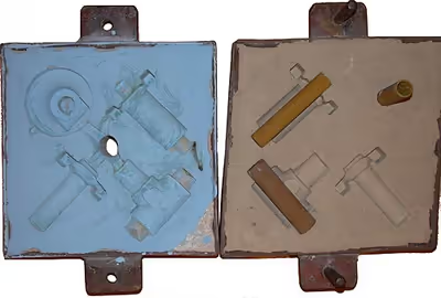
Molds made of sand are relatively cheap, and sufficiently refractory even for steel foundry use. In addition to the sand, a suitable bonding agent (usually clay) is mixed or occurs with the sand. The mixture is moistened, typically with water, but sometimes with other substances, to develop the strength and plasticity of the clay and to make the aggregate suitable for molding. The sand is typically contained in a system of frames or mold boxes known as a flask. The mold cavities and gate system are created by compacting the sand around models called patterns, by carving directly into the sand, or via 3D printing.
Basic process
There are five steps in this process:
- Place a pattern in sand to create a mould.
- Incorporate the pattern and sand in a gating system. Remove the pattern.
- Fill the mold cavity with molten metal.
- Allow the metal to cool.
- Break away the sand mold and remove the casting.
Components
Patterns
From the design, a pattern maker builds a pattern of the object to be produced, using wood, metal, or a plastic such as expanded polystyrene. Sand can be ground, swept or strickled into shape. The metal to be cast will contract during solidification, and this may be non-uniform due to uneven cooling. Therefore, the pattern must be slightly larger than the finished product, a difference known as contraction allowance. Different scaled rules are used for different metals, because each metal and alloy contracts by an amount distinct from all others. Patterns also have core prints that create registers within the molds into which are placed sand cores. Such cores, sometimes reinforced by wires, are used to create under-cut profiles and cavities which cannot be molded with the cope and drag, such as the interior passages of valves or cooling passages in engine blocks.
Paths for the entrance of metal into the mold cavity constitute the runner system and include the sprue, various feeders which maintain a good metal 'feed', and in-gates which attach the runner system to the casting cavity. Gas and steam generated during casting exit through the permeable sand or via risers, which are added either in the pattern itself, or as separate pieces.
Tools
In addition to patterns, the sand molder could also use tools to create the holes.
Molding box and materials
A multi-part molding box (known as a casting flask, the top and bottom halves of which are known respectively as the cope and drag) is prepared to receive the pattern. Molding boxes are made in segments that may be latched to each other and to end closures. For a simple object—flat on one side—the lower portion of the box, closed at the bottom, will be filled with a molding sand. The sand is packed in through a vibratory process called ramming, and in this case, periodically screeded level. The surface of the sand may then be stabilized with a sizing compound. The pattern is placed on the sand and another molding box segment is added. Additional sand is rammed over and around the pattern. Finally a cover is placed on the box and it is turned and unlatched, so that the halves of the mold may be parted and the pattern with its sprue and vent patterns removed. Additional sizing may be added and any defects introduced by the removal of the pattern are corrected. The box is closed again. This forms a "green" mold which must be dried to receive the hot metal. If the mold is not sufficiently dried a steam explosion can occur that can throw molten metal about. In some cases, the sand may be oiled instead of moistened, which makes casting possible without waiting for the sand to dry. Sand may also be bonded by chemical binders, such as furane resins or amine-hardened resins.
Additive manufacturing (AM) can be used in the sand mold preparation, so that instead of the sand mold being formed via packing sand around a pattern, it is 3D-printed. This can reduce lead times for casting by obviating patternmaking. Besides replacing older methods, additive can also complement them in hybrid models, such as making a variety of AM-printed cores for a cavity derived from a traditional pattern.
Chills
To control the solidification structure of the metal, it is possible to place metal plates, chills, in the mold. The associated rapid local cooling will form a finer-grained structure and may form a somewhat harder metal at these locations. In ferrous castings, the effect is similar to quenching metals in forge work. The inner diameter of an engine cylinder is made hard by a chilling core. In other metals, chills may be used to promote directional solidification of the casting. In controlling the way a casting freezes, it is possible to prevent internal voids or porosity inside castings.
Cores
Cores are apparatus used to generate hollow cavities or internal features which cannot be formed using pattern alone in molding, cores are usually made using sand, but some processes also use permanent cores made of metal.
To produce cavities within the casting—such as for liquid cooling in engine blocks and cylinder heads—negative forms are used to produce cores. Usually sand-molded, cores are inserted into the casting box after removal of the pattern. Whenever possible, designs are made that avoid the use of cores, due to the additional set-up time, mass and thus greater cost.
With a completed mold at the appropriate moisture content, the box containing the sand mold is then positioned for filling with molten metal—typically iron, steel, bronze, brass, aluminium, magnesium alloys, or various pot metal alloys, which often include lead, tin, and zinc. After being filled with liquid metal the box is set aside until the metal is sufficiently cool to be strong. The sand is then removed, revealing a rough casting that, in the case of iron or steel, may still be glowing red. In the case of metals that are significantly heavier than the casting sand, such as iron or lead, the casting flask is often covered with a heavy plate to prevent a problem known as floating the mold. Floating the mold occurs when the pressure of the metal pushes the sand above the mold cavity out of shape, causing the casting to fail.
After casting, the cores are broken up by rods or shot and removed from the casting. The metal from the sprue and risers is cut from the rough casting. Various heat treatments may be applied to relieve stresses from the initial cooling and to add hardness—in the case of steel or iron, by quenching in water or oil. The casting may be further strengthened by surface compression treatment—like shot peening—that adds resistance to tensile cracking and smooths the rough surface. And when high precision is required, various machining operations (such as milling or boring) are made to finish critical areas of the casting. Examples of this would include the boring of cylinders and milling of the deck on a cast engine block.
Design requirements
The part to be made and its pattern must be designed to accommodate each stage of the process, as it must be possible to remove the pattern without disturbing the molding sand and to have proper locations to receive and position the cores. A slight taper, known as draft, must be used on surfaces perpendicular to the parting line, in order to be able to remove the pattern from the mold. This requirement also applies to cores, as they must be removed from the core box in which they are formed. The sprue and risers must be arranged to allow a proper flow of metal and gasses within the mold in order to avoid an incomplete casting. Should a piece of core or mold become dislodged it may be embedded in the final casting, forming a sand pit, which may render the casting unusable. Gas pockets can cause internal voids. These may be immediately visible or may only be revealed after extensive machining has been performed. For critical applications, or where the cost of wasted effort is a factor, non-destructive testing methods may be applied before further work is performed.
Sign in to keep reading
3 more chapters are free with a Lably account.
Processes
In general, we can distinguish between two methods of sand casting; the first one using green sand and the second being the air set method.
Green sand
These castings are made using sand molds formed from "wet" sand which contains water and organic bonding compounds, typically referred to as clay. The name "green sand" comes from the fact that the sand mold is not "set", it is still in the "green" or uncured state even when the metal is poured in the mold. Green sand is not green in color, but "green" in the sense that it is used in a wet state (akin to green wood). Contrary to what the name suggests, "green sand" is not a type of sand on its own (that is, not greensand in the geologic sense), but is rather a mixture of:
- silica sand (SiO2), chromite sand (FeCr2O4), or zircon sand (ZrSiO4), 75 to 85%, sometimes with a proportion of olivine, staurolite, or graphite.
- bentonite (clay), 5 to 11%
- water, 2 to 4%
- inert sludge 3 to 5%
- anthracite (0 to 1%)
There are many recipes for the proportion of clay, but they all strike different balances between moldability, surface finish, and ability of the hot molten metal to degas. Coal, typically referred to in foundries as sea-coal, which is present at a ratio of less than 5%, partially combusts in the presence of the molten metal, leading to offgassing of organic vapors. Green sand casting for non-ferrous metals does not use coal additives, since the CO created does not prevent oxidation. Green sand for aluminum typically uses olivine sand (a mixture of the minerals forsterite and fayalite, which is made by crushing dunite rock).
The choice of sand has a lot to do with the temperature at which the metal is poured. At the temperatures that copper and iron are poured, the clay is inactivated by the heat, in that the montmorillonite is converted to illite, which is a non-expanding clay. Most foundries do not have the very expensive equipment to remove the burned out clay and substitute new clay, so instead, those that pour iron typically work with silica sand that is inexpensive compared to the other sands. As the clay is burned out, newly mixed sand is added and some of the old sand is discarded or recycled into other uses. Silica is the least desirable of the sands, since metamorphic grains of silica sand have a tendency to explode to form sub-micron sized particles when thermally shocked during pouring of the molds. These particles enter the air of the work area and can lead to silicosis in the workers. Iron foundries expend considerable effort on aggressive dust collection to capture this fine silica. Various types of respiratory-protective equipment are also used in foundries.
The sand also has the dimensional instability associated with the conversion of quartz from alpha quartz to beta quartz at 680 °C (1250 °F). Often, combustible additives such as wood flour are added to create spaces for the grains to expand without deforming the mold. Olivine, chromite, etc. are therefore used because they do not have a phase transition that causes rapid expansion of the grains. Olivine and chromite also offer greater density, which cools the metal faster, thereby producing finer grain structures in the metal. Since they are not metamorphic minerals, they do not have the polycrystals found in silica, and subsequently they do not form hazardous sub-micron sized particles.
"Air set" method
The air set method uses dry sand bonded with materials other than clay, using a fast curing adhesive. The latter may also be referred to as no bake mold casting. When these are used, they are collectively called "air set" sand castings to distinguish them from "green sand" castings. Two types of molding sand are natural bonded (bank sand) and synthetic (lake sand); the latter is generally preferred due to its more consistent composition.
With both methods, the sand mixture is packed around a pattern, forming a mold cavity. If necessary, a temporary plug is placed in the sand and touching the pattern in order to later form a channel into which the casting fluid can be poured. Air-set molds are often formed with the help of a casting flask having a top and bottom part, termed the cope and drag. The sand mixture is tamped down as it is added around the pattern, and the final mold assembly is sometimes vibrated to compact the sand and fill any unwanted voids in the mold. Then the pattern is removed along with the channel plug, leaving the mold cavity. The casting liquid (typically molten metal) is then poured into the mold cavity. After the metal has solidified and cooled, the casting is separated from the sand mold. There is typically no mold release agent, and the mold is generally destroyed in the removal process.
The accuracy of the casting is limited by the type of sand and the molding process. Sand castings made from coarse green sand impart a rough texture to the surface, and this makes them easy to identify. Castings made from fine green sand can shine as cast but are limited by the depth to width ratio of pockets in the pattern. Air-set molds can produce castings with smoother surfaces than coarse green sand but this method is primarily chosen when deep narrow pockets in the pattern are necessary, due to the expense of the plastic used in the process. Air-set castings can typically be easily identified by the burnt color on the surface. The castings are typically shot blasted to remove that burnt color. Surfaces can also be later ground and polished, for example when making a large bell. After molding, the casting is covered with a residue of oxides, silicates and other compounds. This residue can be removed by various means, such as grinding, or shot blasting.
During casting, some of the components of the sand mixture are lost in the thermal casting process. Green sand can be reused after adjusting its composition to replenish the lost moisture and additives. The pattern itself can be reused indefinitely to produce new sand molds. The sand molding process has been used for many centuries to produce castings manually. Since 1950, partially automated casting processes have been developed for production lines.
Cold box
Cold box uses organic and inorganic binders that strengthen the mold by chemically adhering to the sand. This type of mold gets its name from not being baked in an oven like other sand mold types. This type of mold is more accurate dimensionally than green-sand molds but is more expensive. Thus it is used only in applications that necessitate it.
No-bake molds
No-bake molds are expendable sand molds, similar to typical sand molds, except they also contain a quick-setting liquid resin and catalyst. Rather than being rammed, the molding sand is poured into the flask and held until the resin solidifies, which occurs at room temperature. This type of molding also produces a better surface finish than other types of sand molds. Because no heat is involved it is called a cold-setting process. Common flask materials that are used are wood, metal, and plastic. Common metals cast into no-bake molds are brass, iron (ferrous), and aluminum alloys.
Vacuum molding
Vacuum molding (V-process) is a variation of the sand casting process for most ferrous and non-ferrous metals, in which unbonded sand is held in the flask with a vacuum. The pattern is specially vented so that a vacuum can be pulled through it. A heat-softened thin sheet (0.003 to 0.008 in (0.076 to 0.203 mm)) of plastic film is draped over the pattern and a vacuum is drawn (200 to 400 mmHg (27 to 53 kPa)). A special vacuum forming flask is placed over the plastic pattern and is filled with a free-flowing sand. The sand is vibrated to compact the sand and a sprue and pouring cup are formed in the cope. Another sheet of plastic is placed over the top of the sand in the flask and a vacuum is drawn through the special flask; this hardens and strengthens the unbonded sand. The vacuum is then released on the pattern and the cope is removed. The drag is made in the same way (without the sprue and pouring cup). Any cores are set in place and the mold is closed. The molten metal is poured while the cope and drag are still under a vacuum, because the plastic vaporizes but the vacuum keeps the shape of the sand while the metal solidifies. When the metal has solidified, the vacuum is turned off and the sand runs out freely, releasing the casting.
The V-process is known for not requiring a draft because the plastic film has a certain degree of lubricity and it expands slightly when the vacuum is drawn in the flask. The process has high dimensional accuracy, with a tolerance of ±0.010 in for the first inch and ±0.002 in/in thereafter. Cross-sections as small as 0.090 in (2.3 mm) are possible. The surface finish is very good, usually between 150 and 125 rms. Other advantages include no moisture related defects, no cost for binders, excellent sand permeability, and no toxic fumes from burning the binders. Finally, the pattern does not wear out because the sand does not touch it. The main disadvantage is that the process is slower than traditional sand casting so it is only suitable for low to medium production volumes; approximately 10 to 15,000 pieces a year. However, this makes it perfect for prototype work, because the pattern can be easily modified as it is made from plastic.
Fast mold making processes
With the fast development of the car and machine building industry the casting consuming areas called for steady higher productivity. The basic process stages of the mechanical molding and casting process are similar to those described under the manual sand casting process. The technical and mental development however was so rapid and profound that the character of the sand casting process changed radically.
Mechanized sand molding
The first mechanized molding lines consisted of sand slingers and/or jolt-squeeze devices that compacted the sand in the flasks. Subsequent mold handling was mechanical using cranes, hoists and straps. After core setting the copes and drags were coupled using guide pins and clamped for closer accuracy. The molds were manually pushed off on a roller conveyor for casting and cooling.
Automatic high pressure sand molding lines
Increasing quality requirements made it necessary to increase the mold stability by applying steadily higher squeeze pressure and modern compaction methods for the sand in the flasks. In early fifties the high pressure molding was developed and applied in mechanical and later automatic flask lines. The first lines were using jolting and vibrations to pre-compact the sand in the flasks and compressed air powered pistons to compact the molds.
Horizontal sand flask molding
In the first automatic horizontal flask lines the sand was shot or slung down on the pattern in a flask and squeezed with hydraulic pressure of up to 140 bars. The subsequent mold handling including turn-over, assembling, pushing-out on a conveyor were accomplished either manually or automatically. In the late fifties hydraulically powered pistons or multi-piston systems were used for the sand compaction in the flasks. This method produced much more stable and accurate molds than it was possible manually or pneumatically. In the late sixties mold compaction by fast air pressure or gas pressure drop over the pre-compacted sand mold was developed (sand-impulse and gas-impact). The general working principle for most of the horizontal flask line systems is shown on the sketch below.
Today there are many manufacturers of the automatic horizontal flask molding lines. The major disadvantages of these systems is high spare parts consumption due to multitude of movable parts, need of storing, transporting and maintaining the flasks and productivity limited to approximately 90–120 molds per hour.
Vertical sand flaskless molding
In 1962, Dansk Industri Syndikat A/S (DISA-DISAMATIC) invented a flask-less molding process by using vertically parted and poured molds. The first line could produce up to 240 complete sand molds per hour. Today molding lines can achieve a molding rate of 550 sand molds per hour and requires only one monitoring operator. Maximum mismatch of two mold halves is 0.1 mm (0.0039 in). Although very fast, vertically parted molds are not typically used by jobbing foundries due to the specialized tooling needed to run on these machines. Cores need to be set with a core mask as opposed to by hand and must hang in the mold as opposed to being set on parting surface.
Matchplate sand molding
The principle of the matchplate, meaning pattern plates with two patterns on each side of the same plate, was developed and patented in 1910, fostering the perspectives for future sand molding improvements. However, first in the early sixties the American company Hunter Automated Machinery Corporation launched its first automatic flaskless, horizontal molding line applying the matchplate technology.
The method alike to the DISA's (DISAMATIC) vertical molding is flaskless, however horizontal. The matchplate molding technology is today used widely. Its great advantage is inexpensive pattern tooling, easiness of changing the molding tooling, thus suitability for manufacturing castings in short series so typical for the jobbing foundries. Modern matchplate molding machine is capable of high molding quality, less casting shift due to machine-mold mismatch (in some cases less than 0.15 mm (0.0059 in)), consistently stable molds for less grinding and improved parting line definition. In addition, the machines are enclosed for a cleaner, quieter working environment with reduced operator exposure to safety risks or service-related problems.
Safety standards
With automated mold manufacturing came additional workplace safety requirements. Different voluntary technical standards apply depending on the geopolitical jurisdiction where the machinery is to be used.
Canada
Canada does not have a machine-specific voluntary technical standard for sand-mold making machinery. This type of machinery is covered by:
Safeguarding of machinery, CSA Z432. Canadian Standards Association. 2016.
In addition, the electrical safety requirements are covered by:
Industrial Electrical Machinery, CSA C22.2 No. 301. 2016.
European Union
The primary standard for sand-mold manufacturing equipment in the EU is: Safety requirements for foundry moulding and coremaking machinery and plant associated equipment, EN 710. European Committee for Standardization (CEN).
EN 710 will need to be used in conjunction with EN 60204-1 for electrical safety, and EN ISO 13849-1 and EN ISO 13849-2 or EN 62061 for functional safety. Additional type C standards may also be necessary for conveyors, robotics or other equipment that may be needed to support the operation of the mold-making equipment.
United States
There is no machine-specific standard for sand-mold manufacturing equipment. The ANSI B11 family of standards includes some generic machine-tool standards that could be applied to this type of machinery, including:
- Safety of Machinery, ANSI B11.0. American National Standards Institute (ANSI). 2020.
- Performance Requirements for Risk Reduction Measures: Safeguarding and other Means of Reducing Risk, ANSI B11.19. American National Standards Institute (ANSI). 2019.
- Safety Requirements for the Integration of Machinery into a System, ANSI B11.20. American National Standards Institute (ANSI). 2017.
- Safety Requirements for Transfer Machines, ANSI B11.24. American National Standards Institute (ANSI). 2002 (R2020).
- Functional Safety for Equipment (Electrical/Fluid Power Control Systems) General Principles for the Design of Safety Control Systems Using ISO 13849-1, ANSI B11.26. American National Standards Institute (ANSI). 2018.
- Sound Level Measurement Guidelines, ANSI B11.TR5. American National Standards Institute (ANSI). 2006 (R2017).
Mold materials
There are four main components for making a sand casting mold: base sand, a binder, additives, and a parting compound.
Molding sands
Molding sands, also known as foundry sands, are defined by eight characteristics: refractoriness, chemical inertness, permeability, surface finish, cohesiveness, flowability, collapsibility, and availability/cost.
Refractoriness — This refers to the sand's ability to withstand the temperature of the liquid metal being cast without breaking down. For example, some sands only need to withstand 650 °C (1,202 °F) if casting aluminum alloys, whereas steel needs a sand that will withstand 1,500 °C (2,730 °F). Sand with too low refractoriness will melt and fuse to the casting.
Chemical inertness — The sand must not react with the metal being cast. This is especially important with highly reactive metals, such as magnesium and titanium.
Permeability — This refers to the sand's ability to exhaust gases. This is important because during the pouring process many gases are produced, such as hydrogen, nitrogen, carbon dioxide, and steam, which must leave the mold otherwise casting defects, such as blow holes and gas holes, occur in the casting. For each cubic centimeter of water added to the mold 1600 cc of steam is produced.
Surface finish — The size and shape of the sand particles defines the best surface finish achievable, with finer particles producing a better finish. However, as the particles become finer (and surface finish improves) the permeability becomes worse.
Cohesiveness (or bond) — This is the ability of the sand to retain a given shape after the pattern is removed.
Flowability – The ability for the sand to flow into intricate details and tight corners without special processes or equipment.
Collapsibility — This is the ability of the sand to be easily stripped off the casting after it has solidified. Sands with poor collapsibility will adhere strongly to the casting. When casting metals that significantly contract during cooling or with long freezing temperature ranges a sand with poor collapsibility will cause cracking and hot tears in the casting. Special additives can be used to improve collapsibility.
Availability/cost — The availability and cost of the sand is very important because for every ton of metal poured, three to six tons of sand is required. Although sand can be screened and reused, the particles eventually become too fine and require periodic replacement with fresh sand.
In large castings it is economical to use two different sands, because the majority of the sand will not be in contact with the casting, so it does not need any special properties. The sand that is in contact with the casting is called facing sand, and is designed for the casting on hand. This sand will be built up around the pattern to a thickness of 30 to 100 mm (1.2 to 3.9 in). The sand that fills in around the facing sand is called backing sand. This sand is simply silica sand with only a small amount of binder and no special additives.
Types of base sands
Base sand is the type used to make the mold or core without any binder. Because it does not have a binder it will not bond together and is not usable in this state.
Silica sand
Silica (SiO2) sand is the sand found on a beach and is also the most commonly used sand. It is either made by crushing sandstone or taken from natural occurring locations, such as beaches and river beds. The fusion point of pure silica is 1,760 °C (3,200 °F), however the sands used have a lower melting point due to impurities. For high melting point casting, such as steels, a minimum of 98% pure silica sand must be used; however for lower melting point metals, such as cast iron and non-ferrous metals, a lower purity sand can be used (between 94 and 98% pure).
Silica sand is the most commonly used sand because of its great abundance and low cost. Its disadvantages are high thermal expansion, which can cause casting defects with high melting point metals, and low thermal conductivity, which can lead to unsound casting. It also cannot be used with certain metals because it will chemically interact with the metal, forming surface defects. Finally, it releases silica particulates during the pour, risking silicosis in foundry workers.
Olivine sand
Olivine is a mixture of orthosilicates of iron and magnesium from the mineral dunite. Its main advantage is that it is free from silica, therefore it can be used with basic metals, such as manganese steels. Other advantages include a low thermal expansion, high thermal conductivity, and high fusion point.
Chromite sand
Chromite sand is a solid solution of spinels. Its advantages are a low percentage of silica, a very high fusion point (1,850 °C (3,360 °F)), and a very high thermal conductivity. Its disadvantage is its cost, therefore it is only used with expensive alloy steel casting and to make cores.
Zircon sand
Zircon sand is a compound of approximately two-thirds zirconium oxide (ZrO2) and one-third silica. It has the highest fusion point of all the base sands at 2,600 °C (4,710 °F), a very low thermal expansion, and a high thermal conductivity. Because of these properties it is commonly used when casting alloy steels and other expensive alloys. It is also used as a mold wash (a coating applied to the molding cavity) to improve surface finish. However, it is expensive and not readily available.
Chamotte sand
Chamotte is made by calcining fire clay (Al2O3-SiO2) above 1,100 °C (2,010 °F). Its fusion point is 1,750 °C (3,180 °F) and has low thermal expansion. It is the second cheapest sand, however it is still twice as expensive as silica. Its disadvantages are very coarse grains, which result in a poor surface finish, and it is limited to dry sand molding. Mold washes are used to overcome the surface finish problems. This sand is usually used when casting large steel workpieces.
Binders
Binders are added to a base sand to bond the sand particles together (i.e. it is the glue that holds the mold together).
Clay and water
A mixture of clay and water is the most commonly used binder. There are two types of clay commonly used: bentonite and kaolinite, with the former being the most common.
Oil
Oils, such as linseed oil, other vegetable oils and marine oils, used to be used as a binder, however due to their increasing cost, they have been mostly phased out. The oil also required careful baking at 100 to 200 °C (212 to 392 °F) to cure (if overheated, the oil becomes brittle, wasting the mold).
Resin
Resin binders are natural or synthetic high melting point gums. The two common types used are urea formaldehyde (UF) and phenol formaldehyde (PF) resins. PF resins have a higher heat resistance than UF resins and cost less. There are also cold-set resins, which use a catalyst instead of a heat to cure the binder. Resin binders are quite popular because different properties can be achieved by mixing with various additives. Other advantages include good collapsibility, low gassing, and they leave a good surface finish on the casting.
MDI (methylene diphenyl diisocyanate) is also a commonly used binder resin in the foundry core process.
Sodium silicate
Water glass ( sodium silicate [Na2SiO3 or (Na2O)(SiO2)] ) is a high strength binder used with silica molding sand both for cores and molds. To cure a mixture of finely ground sand (e.g. by using a sand muller) and 3 to 4% of sodium silicate the binder, carbon dioxide (CO2) gas is used. The mixture is exposed to the gas at ambient temperature reacting as following:
The advantage to this binder is that it can be used at room temperature and is fast. The disadvantage is that its high strength leads to shakeout difficulties and possibly hot tears (probably due to quartz inversion) in the casting. The mixed sodium silicate and sand may also be heated by a heat gun to achieve better rigideness.
Additives
Additives are added to the molding components to improve: surface finish, dry strength, refractoriness, and "cushioning properties".
Up to 5% of reducing agents, such as coal powder, pitch, creosote, and fuel oil, may be added to the molding material to prevent wetting (prevention of liquid metal sticking to sand particles, thus leaving them on the casting surface), improve surface finish, decrease metal penetration, and burn-on defects. These additives achieve this by creating gases at the surface of the mold cavity, which prevent the liquid metal from adhering to the sand. Reducing agents are not used with steel casting, because they can carburize the metal during casting.
Up to 3% of "cushioning material", such as wood flour, sawdust, powdered husks, peat, and straw, can be added to reduce scabbing, hot tear, and hot crack casting defects when casting high temperature metals. These materials are beneficial because burn-off when the metal is poured creates tiny voids in the mold, allowing the sand particles to expand. They also increase collapsibility and reduce shakeout time.
Up to 2% of cereal binders, such as dextrin, starch, sulphite lye, and molasses, can be used to increase dry strength (the strength of the mold after curing) and improve surface finish. Cereal binders also improve collapsibility and reduce shakeout time because they burn off when the metal is poured. The disadvantage to cereal binders is that they are expensive.
Up to 2% of iron oxide powder can be used to prevent mold cracking and metal penetration, essentially improving refractoriness. Silica flour (fine silica) and zircon flour also improve refractoriness, especially in ferrous castings. The disadvantages to these additives is that they greatly reduce permeability.
Parting compounds
To get the pattern out of the mold, prior to casting, a parting compound is applied to the pattern to ease removal. They can be a liquid or a fine powder (particle diameters between 75 and 150 micrometres (0.0030 and 0.0059 in)). Common powders include talc, graphite, and dry silica; common liquids include mineral oil and water-based silicon solutions. The latter are more commonly used with metal and large wooden patterns.
History
Clay molds were used in ancient China since the Shang dynasty (c. 1600 to 1046 BC). The famous Houmuwu ding (c. 1300 BC) was made using clay molding.
The Assyrian king Sennacherib (704–681 BC) cast massive bronzes of up to 30 tonnes, and claims to have been the first to have used clay molds rather than the "lost-wax" method:
Whereas in former times the kings my forefathers had created bronze statues imitating real-life forms to put on display inside their temples, but in their method of work they had exhausted all the craftsmen, for lack of skill and failure to understand the principles they needed so much oil, wax and tallow for the work that they caused a shortage in their own countries—I, Sennacherib, leader of all princes, knowledgeable in all kinds of work, took much advice and deep thought over doing that work. Great pillars of bronze, colossal striding lions, such as no previous king had ever constructed before me, with the technical skill that Ninushki brought to perfection in me, and at the prompting of my intelligence and the desire of my heart I invented a technique for bronze and made it skillfully. I created clay moulds as if by divine intelligence....twelve fierce lion-colossi together with twelve mighty bull-colossi which were perfect castings... I poured copper into them over and over again; I made the castings as skillfully as if they had only weighed half a shekel each
In 1206, Ismail al-Jazari first described the casting of metals in closed mold boxes with sand.
Around 1540, sand casting molding method was recorded by Vannoccio Biringuccio in his book.
Between 1702-1707, Abraham Darby I, with John Thomas, improved the technique, using a combination of Green sand, with a casting box, to mass produce thin-walled cookware, being awarded a patent for the improvement.
In 1924, the Ford Motor Company set a record by producing 1 million cars, in the process consuming one-third of the total casting production in the U.S. As the automobile industry grew the need for increased casting efficiency grew. The increasing demand for castings in the growing car and machine building industry during and after World War I and World War II, stimulated new inventions in mechanization and later automation of the sand casting process technology.
There was not one bottleneck to faster casting production but rather several. Improvements were made in molding speed, molding sand preparation, sand mixing, core manufacturing processes, and the slow metal melting rate in cupola furnaces. In 1912, the sand slinger was invented by the American company Beardsley & Piper. In 1912, the first sand mixer with individually mounted revolving plows was marketed by the Simpson Company. In 1915, the first experiments started with bentonite clay instead of simple fire clay as the bonding additive to the molding sand. This increased tremendously the green and dry strength of the molds. In 1918, the first fully automated foundry for fabricating hand grenades for the U.S. Army went into production. In the 1930s the first high-frequency coreless electric furnace was installed in the U.S. In 1943, ductile iron was invented by adding magnesium to the widely used grey iron. In 1940, thermal sand reclamation was applied for molding and core sands. In 1952, the "D-process" was developed for making shell molds with fine, pre-coated sand. In 1953, the hotbox core sand process in which the cores are thermally cured was invented. In 1954, a new core binder—water glass (sodium silicate), hardened with CO2 from ambient air, came out
In the 2010s, additive manufacturing began to be applied to sand mold preparation in commercial production; instead of the sand mold being formed via packing sand around a pattern, it is 3D-printed.