

Mechanical television
Television that relies on a scanning device to display images
- 20 min read
- 3 chapters

Related on Lably
This contrasts with vacuum tube electronic television technology, using electron beam scanning methods, for example, in cathode-ray tube (CRT) televisions. Subsequently, modern solid-state liquid-crystal displays (LCD) and LED displays are now used to create and display television pictures.
Mechanical scanning methods were used in the earliest experimental television systems in the 1920s and 1930s. One of the first experimental wireless television transmissions was by Scottish inventor John Logie Baird on October 2, 1925, in London. By 1928, many radio stations were broadcasting experimental television programs using mechanical systems. However, the technology never produced images of sufficient quality to become popular with the public. Mechanical-scan systems were largely superseded by electronic-scan technology in the mid-1930s, which was used in the first commercially successful television broadcasts that began in the late 1930s. In the U.S., experimental stations such as W2XAB in New York City began broadcasting mechanical television programs in 1931 but discontinued operations on February 20, 1933, until returning with an all-electronic system in 1939.
History
Early research
The first mechanical raster scanning techniques were developed in the 19th century for facsimile, the transmission of still images by wire. Alexander Bain introduced the facsimile machine in 1843 to 1846. Frederick Bakewell demonstrated a working laboratory version in 1851. The first practical facsimile system, working on telegraph lines, was developed and put into service by Giovanni Caselli from 1856 onward.
Willoughby Smith discovered the photoconductivity of the element selenium in 1873, laying the groundwork for the selenium cell, which was used as a pickup in most mechanical scan systems.
As a 23-year-old German university student, Paul Julius Gottlieb Nipkow proposed and patented the Nipkow disk in 1884. This was a spinning disk with a spiral pattern of holes in it, so each hole scanned a line of the image. Although he never built a working model of the system, Nipkow's spinning-disk image rasterizer was the key mechanism used in most mechanical scan systems in both the transmitter and receiver.
In 1885, Henry Sutton in Ballarat, Australia designed what he called a telephane for transmission of images via telegraph wires, based on the Nipkow spinning disk system, selenium photocell, Nicol prisms and Kerr effect cell. Sutton's design was published internationally in 1890. An account of its use to transmit and preserve a still image was published in the Evening Star in Washington in 1896.
Constantin Perskyi had coined the word television in a paper read to the International Electricity Congress at the International World Fair in Paris on August 24, 1900. Perskyi's paper reviewed the existing electromechanical technologies, mentioning the work of Nipkow and others.
The first demonstration of the instantaneous transmission of images was made by a German physicist Ernst Ruhmer, who arranged 25 selenium cells as the picture elements for a television receiver. In late 1909 he announced the transmission of simple images over a telephone wire from the Palace of Justice at Brussels to the city of Liège in Belgium, a distance of 70 miles (115 km). This announced demonstration was described at the time as "the world's first working model of television apparatus". The limited number of elements meant his device was only capable of representing simple geometric shapes, and the cost was very high; at a price of £15 (US$45) per selenium cell, he estimated that a 4,000 cell system would cost £60,000 (US$180,000), and a 10,000 cell mechanism capable of reproducing "a scene or event requiring the background of a landscape" would cost £150,000 (US$450,000). Ruhmer expressed the hope that the 1910 Brussels Exposition Universelle et Internationale would sponsor the construction of an advanced device with significantly more cells, as a showcase for the exposition. However, the estimated expense of £250,000 (US$750,000) proved to be too high.
The publicity generated by Ruhmer's demonstration spurred two French scientists, Georges Rignoux and A. Fournier in Paris, to announce similar research that they had been conducting. A matrix of 64 selenium cells, individually wired to a mechanical commutator, served as an electronic retina. In the receiver, a type of Kerr cell modulated the light and a series of variously angled mirrors attached to the edge of a rotating disc scanned the modulated beam onto the display screen. A separate circuit regulated synchronization. The 8 by 8 pixel resolution in this proof-of-concept demonstration was just sufficient to clearly transmit individual letters of the alphabet. An updated image was transmitted "several times" each second.
In 1911, Boris Rosing and his student Vladimir Zworykin created a system that used a mechanical mirror-drum scanner to transmit, in Zworykin's words, "very crude images" over wires to the Braun tube (cathode-ray tube or CRT) in the receiver. Moving images were not possible because, in the scanner, "the sensitivity was not enough and the selenium cell was very laggy".
Television demonstrations
It was the 1907 invention of the first amplifying vacuum tube, the triode, by Lee de Forest, that made the design practical.
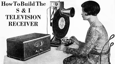
Scottish inventor John Logie Baird in 1925 built some of the first prototype video systems, which employed the Nipkow disk. On March 25, 1925, Baird gave the first public demonstration of televised silhouette images in motion, at Selfridge's Department Store in London. Since human faces had inadequate contrast to show up on his primitive system, he televised a ventriloquist's dummy named "Stooky Bill" talking and moving, whose painted face had higher contrast. By January 26, 1926, he demonstrated the transmission of images of a face in motion by radio. This is widely regarded as being the world's first public television demonstration. Baird's system used the Nipkow disk for both scanning the image and displaying it. A brightly illuminated subject was placed in front of a spinning Nipkow disk set with lenses that swept images across a static photocell. The thallium sulfide (thalofide) cell, developed by Theodore Case in the USA, detected the light reflected from the subject and converted it into a proportional electrical signal. This was transmitted by AM radio waves to a receiver unit, where the video signal was applied to a neon light behind a second Nipkow disk rotating synchronized with the first. The brightness of the neon lamp was varied in proportion to the brightness of each spot on the image. As each hole in the disk passed by, one scan line of the image was reproduced. Baird's disk had 30 holes, producing an image with only 30 scan lines, just enough to recognize a human face.
In 1927, Baird transmitted a signal over 438 miles (705 km) of telephone line between London and Glasgow. In 1928, Baird's company (Baird Television Development Company/Cinema Television) broadcast the first transatlantic television signal between London and New York, and the first shore-to-ship transmission. In 1929, he became involved in the first experimental mechanical television service in Germany. In November of the same year, Baird and Bernard Natan of Pathé established France's first television company, Télévision-Baird-Natan. In 1931, he made the first outdoor remote broadcast of The Derby. In 1932, he demonstrated ultra-short wave television. Baird's mechanical system reached a peak of 240 lines of resolution on BBC television broadcasts in 1936, though the mechanical system did not scan the televised scene directly. Instead, a 17.5 mm film was shot, rapidly developed and then scanned while the film was still wet.
An American inventor, Charles Francis Jenkins also pioneered television. He published an article on "Motion Pictures by Wireless" in 1913, but it was not until December 1923 that he transmitted moving silhouette images for witnesses, and it was on June 13, 1925, that he publicly demonstrated synchronized transmission of silhouette pictures. In 1925, Jenkins used a Nipkow disk and transmitted the silhouette image of a toy windmill in motion over a distance of five miles (8 km) from a naval radio station in Maryland to his laboratory in Washington, D.C., using a lensed disk scanner with a 48-line resolution. He was granted the U.S. patent No. 1,544,156 (Transmitting Pictures over Wireless) on June 30, 1925 (filed March 13, 1922).
On December 25, 1926, Kenjiro Takayanagi demonstrated a television system with a 40-line resolution that employed a Nipkow disk scanner and CRT display at Hamamatsu Industrial High School in Japan. This prototype is still on display at the Takayanagi Memorial Museum in Shizuoka University, Hamamatsu Campus. By 1927, he improved the resolution to 100 lines, which was unrivaled until 1931. By 1928, he was the first to transmit human faces in half-tones. His work had an influence on the later work of Vladimir K. Zworykin. In Japan, he is viewed as the man who completed the first all-electronic television. His research in creating a production model was halted by the US after Japan lost World War II.
Herbert E. Ives and Frank Gray of Bell Telephone Laboratories gave a dramatic demonstration of mechanical television on April 7, 1927. The reflected-light television system included both small and large viewing screens. The small receiver had a 2 by 2+1⁄2 inches (5 by 6 cm) screen, width by height. The large receiver had a screen 24 by 30 inches (60 by 75 cm), width by height. Both sets were capable of reproducing reasonably accurate, monochromatic moving images. Along with the pictures, the sets also received synchronized sound. The system transmitted images over two paths: first, a copper wire link from Washington to New York City, then a radio link from Whippany, New Jersey. Comparing the two transmission methods, viewers noted no difference in quality. Subjects of the telecast included Secretary of Commerce Herbert Hoover. A flying-spot scanner beam illuminated these subjects. The scanner that produced the beam had a 50-aperture disk. The disc revolved at a rate of 18 frames per second, capturing one frame about every 56 ms. (Today's systems typically transmit 30 or 60 frames per second, or one frame every 33.3 or 16.7 ms, respectively.) Television historian Albert Abramson underscored the significance of the Bell Labs demonstration: "It was in fact the best demonstration of a mechanical television system ever made to this time. It would be several years before any other system could even begin to compare with it in picture quality."
In 1928, General Electric launched its own experimental television station W2XB, broadcasting from the GE plant in Schenectady, New York. The station was popularly known as WGY Television, named after the GE-owned radio station WGY. The station eventually converted to an all-electronic system in the 1930s and in 1942, received a commercial license as WRGB. The station is still operating today.
Meanwhile, in the Soviet Union, Léon Theremin had been developing a mirror drum-based television, starting with 16 lines resolution in 1925, then 32 lines and eventually 64 using interlacing in 1926, and as part of his thesis on May 7, 1926, he electrically transmitted and then projected near-simultaneous moving images on a five-foot (1.5 m) square screen. By 1927, he achieved an image of 100 lines, a resolution that was not surpassed until 1931 by RCA, with 120 lines.
Because only a limited number of holes could be made in the disks, and disks beyond a certain diameter became impractical, image resolution on mechanical television broadcasts was relatively low, ranging from about 30 lines up to 120 or so. Nevertheless, the image quality of 30-line transmissions steadily improved with technical advances, and by 1933, the UK broadcasts using the Baird system were remarkably clear. A few systems ranging into the 200-line region also went on the air.
180-lines broadcast tests were carried out by the Reichs-Rundfunk-Gesellschaft in 1935, with a 16 kW transmitter in Berlin. Transmissions lasted 90 minutes a day, three days a week, with sound/visions frequencies being 21.98 and 22.92 feet (6.7 and 6.985 m).
Likewise, a 180-line system that Compagnie des Compteurs (CDC) installed in Paris was tested in 1935, and a 180-line system by Peck Television Corp. started in 1935 at station VE9AK in Montreal, Quebec, Canada.
Color television
John Baird's 1928 color television experiments had inspired Goldmark's more advanced field-sequential color system. The CBS color television system invented by Peter Goldmark used such technology in 1940. In Goldmark's system, stations transmit color saturation values electronically; however, mechanical methods are also used. At the transmitting camera, a mechanical disc filters hues (colors) from reflected studio lighting. At the receiver, a synchronized disc paints the same hues over the CRT. As the viewer watches pictures through the color disc, the pictures appear in full color.
Later, simultaneous color systems superseded the CBS-Goldmark system, but mechanical color methods continued to find uses. Early color sets were very expensive: over $1,000 in the money of the time. Inexpensive adapters allowed owners of black-and-white NTSC television sets to receive color telecasts. The most prominent of these adapters is Col-R-Tel, a 1955 NTSC to field-sequential converter. This system operates at NTSC scanning rates but uses a disc like the obsolete CBS system had. The disc converts the black-and-white set to a field-sequential set. Meanwhile, Col-R-Tel electronics recovers NTSC color signals and sequences them for disc reproduction. The electronics also synchronize the disc to the NTSC system. In Col-R-Tel, the electronics provide the saturation values (chroma). These electronics cause chroma values to superimpose over brightness (luminance) changes of the picture. The disc paints the hues (color) over the picture.
A few years after Col-R-Tel, the Apollo Moon missions also adopted field-sequential techniques. The lunar color cameras all had color wheels. These Westinghouse and later RCA cameras sent field-sequential color television pictures to Earth. The Earth receiving stations included electronic equipment that converted the raw color video signals into the NTSC standard.
Decline
The advancement of vacuum tube electronic television (including image dissectors and other camera tubes and CRTs for the reproducer) marked the beginning of the end for mechanical systems as the dominant form of television. Mechanical TV usually only produced small images. It competed with electronic systems before the 1940s.
Vacuum tube television, first demonstrated in September 1927 in San Francisco by Philo Farnsworth, and then publicly by Farnsworth at the Franklin Institute in Philadelphia in 1934, was rapidly overtaking mechanical television. Farnsworth's system was first used for broadcasting in 1936, reaching 400 to more than 600 lines with fast field scan rates, along with competing systems by Philco and DuMont Laboratories. In 1939, RCA paid Farnsworth $1 million for his patents after ten years of litigation, and RCA began demonstrating all-electronic television at the 1939 World's Fair in New York City. The last mechanical television broadcasts ended in 1939 at stations run by a handful of public universities in the United States.
'Scophony' mechanical display receiver
Early Cathode-Ray Television tube displays were small in size. The 'Scophony' television receiver of 1938, an advanced television receiver that used a mechanical display, was capable of displaying a 405-line picture (compatible with the then 405-line television system used in the United Kingdom) on a display that was 24-inch (60 cm) wide and 20-inch (50 cm) high. A version intended for theater audiences had a 6-foot (1.8 m) wide display. It was also capable of being set up for the US 441-line television system. For 405 lines, it used a high-speed scanner running at 30,375 rpm and a low-speed mirror drum running at around 250 rpm, in conjunction with a Jeffree cell to modulate a focused light beam from a mercury lamp. It used 39 vacuum tubes in its electronic circuits and consumed around 1,000 W. Although it produced impressive results and reached the marketplace, the receiver was very expensive, costing around twice as much as a cathode-ray television. It was not a commercial success, and television transmissions in the UK were suspended for the duration of the Second World War, sealing its fate. No complete receiver survives, although some components do.
Modern applications of mechanical scanning
Since the 1970s, some amateur radio enthusiasts have experimented with mechanical systems. The early light source of a neon lamp has now been replaced with super-bright LEDs. There is some interest in creating these systems for narrow-bandwidth television, which would allow a small or large moving image to fit into a channel less than 40 kHz wide (modern TV systems usually have a channel about 6 MHz wide, 150 times larger). Also associated with this is slow-scan TV – although that typically used electronic systems utilising the P7 CRT until the 1980s and PCs thereafter. There are three known mechanical monitor forms: two fax printer-like monitors made in the 1970s, and in 2013 a small drum monitor with a coating of glow paint where the image is painted on the rotating drum with a UV laser.
Digital light processing (DLP) projectors use an array of tiny (16 μm2) electrostatically-actuated mirrors selectively reflecting a light source to create an image. Many low-end DLP systems also use a color wheel to provide a sequential color image, a feature that was common on many early color television systems before the shadow mask CRT provided a practical method for producing a simultaneous color image.
Another place where high-quality imagery is produced by opto-mechanics is the laser printer, where a small rotating mirror is used to deflect a modulated laser beam in one axis while the motion of the photoconductor provides the motion in the other axis. A modification of such a system using high-power lasers is used in laser video projectors, with resolutions as high as 1,024 lines and each line containing over 1,500 points. Such systems produce, arguably, the best quality video images. They are used, for instance, in planetariums.
Mechanical techniques are also used in long-wave infrared cameras used in military applications such as night vision for fighter pilots. These cameras use a high-sensitivity infrared photo receptor (usually cooled to increase sensitivity), but instead of conventional lenses, these systems use rotating prisms to provide a 525 or 625-line standard video output. The optical parts are made from germanium because glass is opaque at the wavelengths involved. Similar cameras have also found a role in sporting events where they are able to show (for example) where a ball has struck a bat.
Laser lighting display techniques are combined with computer emulation in the LaserMAME project. It is a vector-based system, unlike the raster displays thus-far described. Laser light reflected from computer-controlled mirrors traces out images generated by classic arcade software, which is executed by a specially modified version of the MAME emulation software.
Sign in to keep reading
2 more chapters are free with a Lably account.
Technical aspects
Flying spot scanners
The most common method for creating the video signal was the flying spot scanner, developed as a remedy for the low sensitivity that photoelectric cells had at the time. Instead of a television camera that took pictures, a flying spot scanner projected a bright spot of light that scanned rapidly across the subject scene in a raster pattern, in a darkened studio. The light reflected from the subject was picked up by banks of photoelectric cells and amplified to become the video signal.
In the scanner, the narrow light beam was produced by an arc lamp shining through the holes in a spinning Nipkow disk. Each sweep of the spot across the scene produced a scan line of the picture. A single frame of the picture was typically made up of 24, 48, or 60 scan lines. The scene was typically scanned 15 or 20 times per second, producing 15 or 20 video frames per second. The varying brightness of the point where the spot fell reflected varying amounts of light, which was converted to a proportionally varying electronic signal by the photoelectric cells. To achieve adequate sensitivity, instead of a single cell, a number of photoelectric cells were used. Like mechanical television itself, flying spot technology grew out of phototelegraphy (facsimile). This scanning method began in the 19th century.
The flying spot method has two disadvantages:
- Actors must perform in near darkness
- Flying spot cameras tend to work unreliably outdoors in daylight
In 1928, Ray Kell from the United States' General Electric proved that flying spot scanners could work outdoors. The scanning light source must be brighter than other incident illumination.
Kell was the engineer who ran a 24-line camera that telecast pictures of New York governor Al Smith. Smith was accepting the Democratic nomination for the presidency. As Smith stood outside the capital in Albany, Kell managed to send usable pictures to his associate Bedford at station WGY, which was broadcasting Smith's speech. The rehearsal went well, but then the real event began. The newsreel cameramen switched on their floodlights.
Unfortunately for Kell, his scanner only had a 1 kW lamp inside it. The floodlights threw much more light on Governor Smith. These floods simply overwhelmed Kell's imaging photocells. In fact, the floods made the unscanned part of the image as bright as the scanned part. Kell's photocells couldn't discriminate between reflections off Smith (from the AC scanning beam) and the flat, DC light from the floodlamps.
The effect is very similar to extreme overexposure in a still camera: The scene disappears, and the camera records a flat, bright light. If used in favorable conditions, however, the picture comes out correctly. Similarly, Kell proved that outdoors in favorable conditions, his scanner worked.
The BBC television service used the flying spot method until 1935, and German television used flying spot methods as late as 1938. However, flying spot techniques remained in use in many applications after the demise of mechanical television. The German inventor Manfred von Ardenne designed a flying spot scanner with a CRT as the light source, and CRT-based flying spot scanners became a common technique for telecine. In the 1950s, DuMont marketed Vitascan, an entire flying-spot color studio system. Laser scanners continue to use a flying spot approach.
Larger videos
A few mechanical TV systems could produce images several feet or meters wide and of comparable quality to the CRT televisions that were to follow. CRT technology at that time was limited to small, low-brightness screens. One such system was developed by Ulises Armand Sanabria in Chicago. By 1934, Sanabria demonstrated a projection system that had a 30-foot (10 m) image.
Perhaps the best mechanical televisions of the 1930s used the Scophony system, which could produce images of more than 400 lines and display them on screens at least 9 by 12 feet (2.7 m × 3.7 m) in size (at least a few models of this type were actually produced).
The Scophony system used multiple drums rotating at fairly high speed to create the images. One using a 441-line American standard of the day had a small drum rotating at 39,690 rpm (a second slower drum moved at just a few hundred rpm).
Aspect ratios
Some mechanical equipment scanned lines vertically rather than horizontally, as in modern TVs. An example of this method is the Baird 30-line system. Baird's British system created a picture in the shape of a very narrow, vertical rectangle.
This shape created a portrait image, instead of the landscape orientation – these terms coming from the concepts of portrait and landscape in art – that is common today. The position of a framing mask before the Nipkow disk determines the scan line orientation. Placement of the framing mask at the left or right side of the disk gives vertical scan lines. Placement at the top or bottom of the disk gives horizontal scan lines.
Baird's earliest television images had very low definition. These images could only show one person clearly. For this reason, a vertical portrait image made more sense to Baird than a horizontal landscape image. Baird chose a shape three units wide by seven high. This shape is only about half as wide as a traditional portrait and close in proportion to a typical doorway.
Instead of entertainment television, Baird might have had point-to-point communication in mind. Another television system followed that reasoning. The 1927 system developed by Herbert E. Ives at AT&T's Bell Laboratories was a large-screen television system and the most advanced television of its day. The Ives 50-line system also produced a vertical portrait picture. Since AT&T intended to use television for telephony, the vertical shape was logical: phone calls are usually conversations between just two people. A picturephone system would depict one person on each side of the line.
Meanwhile, in the US, Germany and elsewhere, other inventors planned to use television for entertainment purposes. These inventors began with square or landscape pictures. (For example, the television systems of Ernst Alexanderson, Frank Conrad, Charles Francis Jenkins, William Peck and Ulises Armand Sanabria.) These inventors realized that television is about relationships between people. From the very beginning, these inventors allowed picture space for two-shots. Soon, images increased to 60 lines or more. The camera could easily photograph several people at once. Then, even Baird switched his picture mask to a horizontal image. Baird's zone television is an early example of rethinking his extremely narrow screen format. For entertainment and most other purposes, even today, landscape remains the more practical shape.
Recording
In the days of commercial mechanical television transmissions, a system of recording images (but not sound) was developed using a modified gramophone recorder. Marketed as Phonovision, this system, which was never fully perfected, proved to be complicated to use as well as quite expensive, yet managed to preserve a number of early broadcast images that would otherwise have been lost. Scottish computer engineer Donald F. McLean has painstakingly reconstructed the analog playback technology required to view these recordings and has given lectures and presentations on his collection of mechanical television recordings made between 1925 and 1933.
Among the discs in Dr. McLean's collection are a number of test recordings made by television pioneer John Logie Baird himself. One disc, dated "28th March 1928" and marked with the title "Miss Pounsford", shows several minutes of a woman's face in what appears to be very animated conversation. In 1993, the woman was identified by relatives as Mabel Pounsford, and her brief appearance on the disc is one of the earliest known television video recordings of a human.