


Related on Lably
Through Wi-Fi and Bandwidth (computing)
Compared to earlier standards, PCIe supports faster data transfer, uses fewer pins, takes up less space, and allows devices to be added or removed while the computer is running (hot swapping). It also includes better error detection and supports newer features like I/O virtualization for advanced computing needs.
PCIe connections are made through lanes, which are pairs of conductors that send and receive data. Devices can use one or more lanes depending on how much data they need to transfer. PCIe technology is also used in laptop expansion cards (like ExpressCard) and in storage connectors such as M.2, U.2, and SATA Express.
Architecture
Conceptually, the PCI Express bus is a high-speed serial replacement of the older PCI/PCI-X bus. One of the key differences between the PCI Express bus and the older PCI is the bus topology; PCI uses a shared parallel bus architecture, in which the PCI host and all devices share a common set of address, data, and control lines. In contrast, PCI Express is based on point-to-point topology, with separate serial links connecting every device to the root complex (host). Because of its shared bus topology, access to the older PCI bus is arbitrated (in the case of multiple masters), and limited to one master at a time, in a single direction. Furthermore, the older PCI clocking scheme limits the bus clock to the slowest peripheral on the bus (regardless of the devices involved in the bus transaction). In contrast, a PCI Express bus link supports full-duplex communication between any two endpoints, with no inherent limitation on concurrent access across multiple endpoints.
In terms of bus protocol, PCI Express communication is encapsulated in packets. The work of packetizing and de-packetizing data and status-message traffic is handled by the transaction layer of the PCI Express port (described later). Radical differences in electrical signaling and bus protocol require the use of a different mechanical form factor and expansion connectors (and thus, new motherboards and new adapter boards); PCI slots and PCI Express slots are not interchangeable. At the software level, PCI Express preserves backward compatibility with PCI; legacy PCI system software can detect and configure newer PCI Express devices without explicit support for the PCI Express standard, though new PCI Express features are inaccessible.
The PCI Express link between two devices can vary in size from one to 16 lanes. In a multi-lane link, the packet data is striped across lanes, and peak data throughput scales with the overall link width. The lane count is automatically negotiated during device initialization and can be restricted by either endpoint. For example, a single-lane PCI Express (x1) card can be inserted into a multi-lane slot (x4, x8, etc.), and the initialization cycle auto-negotiates the highest mutually supported lane count. The link can dynamically down-configure itself to use fewer lanes, providing a failure tolerance in case bad or unreliable lanes are present. The PCI Express standard defines link widths of x1, x2, x4, x8, and x16. Up to and including PCIe 5.0, x12, and x32 links were defined as well but virtually never used. This allows the PCI Express bus to serve both cost-sensitive applications where high throughput is not needed, and performance-critical applications such as 3D graphics, networking (10 Gigabit Ethernet or multiport Gigabit Ethernet), and enterprise storage (SAS or Fibre Channel). Slots and connectors are only defined for a subset of these widths, with link widths in between using the next larger physical slot size.
As a point of reference, a PCI-X (133 MHz 64-bit) device and a PCI Express 1.0 device using four lanes (x4) have roughly the same peak single-direction transfer rate of 1064 MB/s. The PCI Express bus has the potential to perform better than the PCI-X bus in cases where multiple devices are transferring data simultaneously, or if communication with the PCI Express peripheral is bidirectional.
Interconnect
PCI Express devices communicate via a logical connection called an interconnect or link. A link is a point-to-point communication channel between two PCI Express ports allowing both of them to send and receive ordinary PCI requests (configuration, I/O or memory read/write) and interrupts (INTx, MSI or MSI-X). At the physical level, a link is composed of one or more lanes. Low-speed peripherals (such as an 802.11 Wi-Fi card) use a single-lane (x1) link, while a graphics adapter typically uses a much wider and therefore faster 16-lane (x16) link.
Lane
A lane is composed of two differential signaling pairs, with one pair for receiving data and the other for transmitting. Thus, each lane is composed of four wires or signal traces. Conceptually, each lane is used as a full-duplex byte stream, transporting data packets in eight-bit "byte" format simultaneously in both directions between endpoints of a link. Physical PCI Express links may contain 1, 4, 8 or 16 lanes. Lane counts are written with an "x" prefix (for example, "x8" represents an eight-lane card or slot), with x16 being the largest size in common use. Lane sizes are also referred to via the terms "width" or "by" e.g., an eight-lane slot could be referred to as a "by 8" or as "8 lanes wide."
For mechanical card sizes, see below.
Serial bus
The bonded serial bus architecture was chosen over the traditional parallel bus because of the inherent limitations of the latter, including half-duplex operation, excess signal count, and inherently lower bandwidth due to timing skew. Timing skew results from separate electrical signals within a parallel interface traveling through conductors of different lengths, on potentially different printed circuit board (PCB) layers, and at possibly different signal velocities. Despite being transmitted simultaneously as a single word, signals on a parallel interface have different travel duration and arrive at their destinations at different times. When the interface clock period is shorter than the largest time difference between signal arrivals, recovery of the transmitted word is no longer possible. Since timing skew over a parallel bus can amount to a few nanoseconds, the resulting bandwidth limitation is in the range of hundreds of megahertz.
A serial interface does not exhibit timing skew because there is only one differential signal in each direction within each lane, and there is no external clock signal since clocking information is embedded within the serial signal itself. As such, typical bandwidth limitations on serial signals are in the multi-gigahertz range. PCI Express is one example of the general trend toward replacing parallel buses with serial interconnects; other examples include Serial ATA (SATA), USB, Serial Attached SCSI (SAS), FireWire (IEEE 1394), and RapidIO. In digital video, examples in common use are DVI, HDMI, and DisplayPort, but they were replacements for analog VGA, not for a parallel bus.
Multichannel serial design increases flexibility with its ability to allocate fewer lanes for slower devices.
Switch
A PCIe switch is like a network switch, except that it works with PCIe connections. In the tree topology is one upstream port where it connects to a higher-level device (another switch or directly a PCIe bus) and a number of downstream ports. The switch is responsible for receiving a packet from one port and forwarding it to an appropriate, different port. By doing packet-switching, the bandwidth is effectively shared across multiple downstream ports (compared to static lane bifurcation). A more advanced multi-host topology contains multiple upstream ports.
Sign in to keep reading
7 more chapters are free with a Lably account.
Form factors
PCI Express add-in card
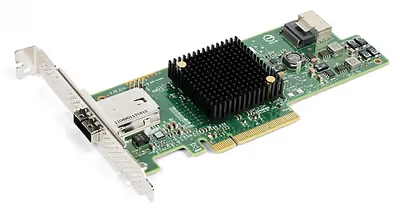
A PCI Express add-in card fits into a slot of its physical size or larger (with x16 as the largest used), but may not fit into a smaller PCI Express slot; for example, a x16 card may not fit into a x4 or x8 slot. Some slots use open-ended sockets to permit physically longer cards and negotiate the best available electrical and logical connection.
The number of lanes actually connected to a slot may also be fewer than the number supported by the physical slot size. An example is a x16 slot that runs at x4, which accepts any x1, x2, x4, x8 or x16 card, but provides only four lanes. Its specification may read as "x16 (x4 mode)" or "x16 (x4 signal)", while "mechanical @ electrical" notation (e.g. "x16 @ x4") is also common. The advantage is that such slots can accommodate a larger range of PCI Express cards without requiring motherboard hardware to support the full transfer rate. Standard mechanical sizes are x1, x4, x8, and x16. Cards using a number of lanes other than the standard mechanical sizes need to physically fit the next larger mechanical size (e.g. an x2 card uses the x4 size, or an x12 card uses the x16 size).
The cards themselves are designed and manufactured in various sizes. For example, solid-state drives (SSDs) that come in the form of PCI Express cards often use HHHL (half height, half length) and FHHL (full height, half length) to describe the physical dimensions of the card. The concept of "full" and "half" heights and lengths are inherited from Conventional PCI.
The length levels beside full are not a PCIe standard, but only a manufacturer agreement. Half length provides sufficient space for a x16 connector. Below that narrower data connectors need to be used.
These dimensions can be freely mixed and matched, but larger dimensions tend to co-occur.
There is a fixed distance of 57.15 millimetres (2.250 in) between the connector's key notch (middle ridge diving data and power) and the end of the card, which may be covered by an end plate with a screw-hole for installing onto the computer case. This fixed length ensures that cards do not protrude out of the chassis.
The slot spacing is exactly 0.8 inches (20 mm) on ATX motherboards.
For further specifications of the slot, see #Physical layer below.
Non-standard video card form factors
Modern (since c. 2012) gaming video cards usually exceed the height as well as thickness specified in the PCI Express standard, due to the need for more capable and quieter cooling fans, as gaming video cards often emit hundreds of watts of heat. Modern computer cases are often wider to accommodate these taller cards, but not always. Since full-length cards (312 mm) are uncommon, modern cases sometimes cannot accommodate them. The thickness of these cards also typically occupies the space of 2 to 5 PCIe slots. In fact, even the methodology of how to measure the cards varies between vendors, with some including the metal bracket size in dimensions and others not.
For instance, comparing three high-end video cards released in 2020: a Sapphire Radeon RX 5700 XT card measures 135 mm in height (excluding the metal bracket), which exceeds the PCIe standard height by 28 mm, another Radeon RX 5700 XT card by XFX measures 55 mm thick (i.e. 2.7 PCI slots at 20.32 mm), taking up 3 PCIe slots, while an Asus GeForce RTX 3080 video card takes up two slots and measures 140.1 mm × 318.5 mm × 57.8 mm, exceeding PCI Express's maximum height, length, and thickness respectively.
Pinout
The following table identifies the conductors on each side of the edge connector on a PCI Express card. The solder side of the printed circuit board (PCB) is the A-side, and the component side is the B-side. PRSNT1# and PRSNT2# pins must be slightly shorter than the rest, to ensure that a hot-plugged card is fully inserted. The WAKE# pin uses full voltage to wake the computer, but must be pulled high from the standby power to indicate that the card is wake capable.
Power
Slot power
All PCI express cards may consume up to 3 A at +3.3 V (9.9 W). The amount of +12 V and total power they may consume depends on the form factor and the role of the card:
- x1 cards are limited to 0.5 A at +12 V (6 W) and 10 W combined.
- x4 and wider cards are limited to 2.1 A at +12 V (25 W) and 25 W combined.
- A full-sized x1 card may draw up to the 25 W limits after initialization and software configuration as a high-power device.
- A full-sized x16 graphics card may draw up to 5.5 A at +12 V (66 W) and 75 W combined after initialization and software configuration as a high-power device.
6- and 8-pin power connectors
Optional connectors add 75 W (6-pin) or 150 W (8-pin) of +12 V power for up to 300 W total (2 @ 75 W + 1 @ 150 W).
- Sense0 pin is connected to ground by the cable or power supply, or float on board if cable is not connected.
- Sense1 pin is connected to ground by the cable or power supply, or float on board if cable is not connected.
Some cards use two 8-pin connectors, allowing 375 W total (1 @ 75 W + 2 @ 150 W). This was newly standardized in PCI Express 4.0 CEM of 2018, though it was already in use before then. The 8-pin PCI Express connector should not be confused with the EPS12V connector, which is mainly used for powering SMP and multi-core systems. The power connectors are variants of the Molex Mini-Fit Jr. series connectors.
12VHPWR connector
The 16-pin 12VHPWR connector is a standard for connecting graphics processing units (GPUs) to computer power supplies for up to 600 W power delivery. It was introduced by Nvidia in 2022 to supersede the previous 6- and 8-pin power connectors for GPUs. The stated aim was to cater to the increasing power requirements of Nvidia GPUs. The connector was formally adopted as part of PCI Express 5.
The connector was replaced by a minor revision called 12V-2x6, introduced in 2023 with PCIe CEM 5.1 and PCIe ECN 6.0, which changed the GPU- and PSU-side sockets to ensure that the sense pins only make contact if the power pins are seated properly. The cables and their plugs remained unchanged. The change is intended to prevent melting due to partial contact, but melting continued to be reported for GPUs with this new socket. There is a significant change in power negotiation with a new sense pin added.
12VHPWR connectors are marked with an "H+" symbol, whereas 12V-2x6 connectors are marked with an "H++" symbol.
48VHPWR connector
In 2021, PCIe Card Electromechanical (CEM, pronounced like "chem" in "chemistry") Specification introduced a connector for 48 Volts with two current-carrying contacts and four sense pins. It was retained into PCIe-CEM 5.1 of 2023. The contacts are rated for 15 Amps continuous current. The 48VHPWR connector can carry 720 watts.
Later it was removed and an incompatible 48V 1×2 connector was introduced where Sense0 and Sense1 are located farthest from each other.
Power excursion
Power excursion refers to short peaks of power draw exceeding the rated maximum (sustained) power level. Since an add-on Engineering Change Notice (ECN) to PCIe-CEM 5.0, the additional power connectors need to be able to handle 100-microsecond power draw at 3× of maximum sustained power, reducing to 1× at the 1-second window level following a logarithmic line. Since PCIe-ECM 5.1, slot power has a similar excursion expansion at 2.5× over 100 μs. In CEM 5.1, the added excursion limit is only provided after software configuration, specifically the Set_Slot_Power_Limit message. The ECN is part of ATX 3.0 and PCIe CEM 5.1 is part of ATX 3.1.
PCI Express Mini Card
PCI Express Mini Card (also known as Mini PCI Express, Mini PCIe, Mini PCI-E, mPCIe, and PEM), based on PCI Express, is a replacement for the Mini PCI form factor. It is developed by the PCI-SIG. The host device supports both PCI Express and USB 2.0 connectivity, and each card may use either standard. Most laptop computers built between 2005 and 2013 use Mini PCI Express for expansion cards; however, as of 2015, many vendors have moved toward using the newer M.2 form factor for this purpose.
Due to different dimensions, PCI Express Mini Cards are not physically compatible with standard full-size PCI Express slots; however, passive adapters exist that let them be used in full-size slots.
Physical dimensions
Dimensions of PCI Express Mini Cards are 30 mm × 50.95 mm (width × length) for a Full Mini Card. There is a 52-pin edge connector, consisting of two staggered rows on a 0.8 mm pitch. Each row has eight contacts, a gap equivalent to four contacts, then a further 18 contacts. Boards have a thickness of 1.0 mm, excluding the components. A "Half Mini Card" (sometimes abbreviated as HMC) is also specified, having approximately half the physical length of 26.8 mm. There are also half size mini PCIe cards that are 30 × 31.90 mm which is about half the length of a full size mini PCIe card.
Electrical interface
PCI Express Mini Card edge connectors provide multiple connections and buses:
- PCI Express x1 (with SMBus)
- USB 2.0
- Wires to diagnostics LEDs for wireless network (i.e., Wi-Fi) status on computer's chassis
- SIM card for GSM and WCDMA applications (UIM signals on spec.)
- Future extension for another PCIe lane
- 1.5 V and 3.3 V power
Mini-SATA (mSATA) variant
Despite sharing the Mini PCI Express form factor, an mSATA slot is not necessarily electrically compatible with Mini PCI Express. For this reason, only certain notebooks are compatible with mSATA drives. Most compatible systems are based on Intel's Sandy Bridge processor architecture, using the Huron River platform. Notebooks such as Lenovo's ThinkPad T, W and X series, released in March–April 2011, have support for an mSATA SSD card in their WWAN card slot. The ThinkPad Edge E220s/E420s, and the Lenovo IdeaPad Y460/Y560/Y570/Y580 also support mSATA. On the contrary, the L-series among others can only support M.2 cards using the PCIe standard in the WWAN slot.
Some notebooks (notably the Asus Eee PC, the Apple MacBook Air, and the Dell mini9 and mini10) use a variant of the PCI Express Mini Card as an SSD. This variant uses the reserved and several non-reserved pins to implement SATA and IDE interface passthrough, keeping only USB, ground lines, and sometimes the core PCIe x1 bus intact. This makes the "miniPCIe" flash and solid-state drives sold for netbooks largely incompatible with true PCI Express Mini implementations.
Also, the typical Asus miniPCIe SSD is 71 mm long, causing the Dell 51 mm model to often be (incorrectly) referred to as half length. A true 51 mm Mini PCIe SSD was announced in 2009, with two stacked PCB layers that allow for higher storage capacity. The announced design preserves the PCIe interface, making it compatible with the standard mini PCIe slot. No working product has yet been developed.
Intel has numerous desktop boards with the PCIe x1 Mini-Card slot that typically do not support mSATA SSD. A list of desktop boards that natively support mSATA in the PCIe x1 Mini-Card slot (typically multiplexed with a SATA port) is provided on the Intel Support site.
PCI Express M.2
M.2 replaces the mSATA standard and Mini PCIe. Computer bus interfaces provided through the M.2 connector are PCI Express 3.0 or higher (up to four lanes), Serial ATA 3.0, and USB 3.0 (a single logical port for each of the latter two). It is up to the manufacturer of the M.2 host or device to choose which interfaces to support, depending on the desired level of host support and device type.
PCI Express External Cabling
PCI Express External Cabling (also known as External PCI Express, Cabled PCI Express, or ePCIe) specifications were released by the PCI-SIG in February 2007.
Standard cables and connectors have been defined for x1, x4, x8, and x16 link widths, with a transfer rate of 250 MB/s per lane. The PCI-SIG also expects the norm to evolve to reach 500 MB/s, as in PCI Express 2.0. An example of the uses of Cabled PCI Express is a metal enclosure, containing a number of PCIe slots and PCIe-to-ePCIe adapter circuitry. This device would not be possible had it not been for the ePCIe specification.
PCI Express OCuLink
OCuLink (standing for "optical-copper link", as Cu is the chemical symbol for copper) is an extension for the "cable version of PCI Express". Version 1.0 of OCuLink, released in Oct 2015, supports up to 4 PCIe 3.0 lanes (3.9 GB/s) over copper cabling; a fiber optic version may appear in the future.
The most recent version of OCuLink, OCuLink-2, supports 8 GB/s or 16 GB/s (PCIe 4.0 x4 or x8) while the maximum bandwidth of a USB (USB4 Gen 4) or Thunderbolt 5 connection is 10 GB/s.
OCulink is principally intended for PCIe (or SATA breakout) interconnections in servers, but also finds limited adoption on laptops for the connection of external GPU boxes.
CopprLink
CopprLink uses SFF-TA-1032 connectors to support external PCIe cable for PCIe 5.0 x16 and PCIe 6.0 x16.
Derivative forms
Numerous other form factors use, or are able to use, PCIe. These include:
- Low-height card
- ExpressCard: Successor to the PC Card form factor (with x1 PCIe and USB 2.0; hot-pluggable)
- PCI Express ExpressModule: A hot-pluggable modular form factor defined for servers and workstations
- XQD card: A PCI Express-based flash card standard by the CompactFlash Association with x2 PCIe
- CFexpress card: A PCI Express-based flash card by the CompactFlash Association in three form factors supporting 1 to 4 PCIe lanes
- SD card: The SD Express bus, introduced in version 7.0 of the SD specification uses a x1 PCIe link
- XMC: Similar to the CMC/PMC form factor (VITA 42.3)
- AdvancedTCA: A complement to CompactPCI for larger applications; supports serial based backplane topologies
- AMC: A complement to the AdvancedTCA specification; supports processor and I/O modules on ATCA boards (x1, x2, x4 or x8 PCIe).
- FeaturePak: A tiny expansion card format (43 mm × 65 mm) for embedded and small-form-factor applications, which implements two x1 PCIe links on a high-density connector along with USB, I2C, and up to 100 points of I/O
- Universal IO: A variant from Super Micro Computer Inc designed for use in low-profile rack-mounted chassis. It has the connector bracket reversed so it cannot fit in a normal PCI Express socket, but it is pin-compatible and may be inserted if the bracket is removed.
- M.2 (formerly known as NGFF)
- M-PCIe brings PCIe 3.0 to mobile devices (such as tablets and smartphones), over the M-PHY physical layer.
- Serial Attached SCSI-related ports:
- SATA Express, U.2 (formerly known as SFF-8639), U.3 use the same port
- SlimSAS (SFF-8654)
- SFF-TA-1016 (M-XIO connector)
- SFF-TA-1026, SFF-TA-1033
The PCIe slot connector can also carry protocols other than PCIe. Some 9xx series Intel chipsets support Serial Digital Video Out, a proprietary technology that uses a slot to transmit video signals from the host CPU's integrated graphics instead of PCIe, using a supported add-in.
The PCIe transaction-layer protocol can also be used over some other interconnects, which are not electrically PCIe:
- Thunderbolt: A royalty-free (as of Thunderbolt 3) interconnect standard by Intel that combines DisplayPort and PCIe protocols in a form factor compatible with Mini DisplayPort. Thunderbolt 3.0 also combines USB 3.1 and uses the USB-C form factor as opposed to Mini DisplayPort.
- USB4 is an extension of Thunderbolt 3.0. Thunderbolt 4 and Thunderbolt 5 are profiles of USB4 specifying higher levels of mandatory features.
History and revisions
While in early development, PCIe was initially referred to as HSI (for High Speed Interconnect), and underwent a name change to 3GIO (for 3rd Generation I/O) before finally settling on its PCI-SIG name PCI Express. A technical working group named the Arapaho Work Group (AWG) drew up the standard. For initial drafts, the AWG consisted only of Intel engineers; subsequently, the AWG expanded to include industry partners.
Since, PCIe has undergone several large and smaller revisions, improving on performance and other features.
Comparison table
- Notes
PCI Express 1.0a
In 2003, PCI-SIG introduced PCIe 1.0a, with a per-lane data rate of 0.25 gigabytes per second (GB/s) and a transfer rate of 2.5 gigatransfers per second (GT/s).
Transfer rate is expressed in transfers per second instead of bits per second because the number of transfers includes the overhead bits, which do not provide additional throughput; PCIe 1.x uses an 8b/10b encoding scheme, resulting in a 20% (= 2/10) overhead on the raw channel bandwidth. So in the PCIe terminology, transfer rate refers to the encoded bit rate: 2.5 GT/s is 2.5 Gbit/s on the encoded serial link. This corresponds to 2.0 Gbit/s of pre-coded data or 0.25 GB/s, which is referred to as throughput in PCIe.
PCI Express 1.1
In 2005, PCI-SIG introduced PCIe 1.1. This updated specification includes clarifications and several improvements, but is fully compatible with PCI Express 1.0a. No changes were made to the data rate.
PCI Express 2.0
PCI-SIG announced the availability of the PCI Express Base 2.0 specification on 15 January 2007. The PCIe 2.0 standard doubles the transfer rate compared with PCIe 1.0 to 5 GT/s and the per-lane throughput rises from 250 MB/s to 500 MB/s. Consequently, a 16-lane PCIe connector (x16) can support an aggregate throughput of up to 8 GB/s.
PCIe 2.0 motherboard slots are fully backward compatible with PCIe v1.x cards. PCIe 2.0 cards are also generally backward compatible with PCIe 1.x motherboards, using the available bandwidth of PCI Express 1.1. Overall, graphic cards or motherboards designed for v2.0 work, with the other being v1.1 or v1.0a.
The PCI-SIG also said that PCIe 2.0 features improvements to the point-to-point data transfer protocol and its software architecture.
Intel's first PCIe 2.0 capable chipset was the X38 and boards began to ship from various vendors (Abit, Asus, Gigabyte) as of 21 October 2007. AMD started supporting PCIe 2.0 with its AMD 700 chipset series and nVidia started with the MCP72. All of Intel's prior chipsets, including the Intel P35 chipset, supported PCIe 1.1 or 1.0a.
Like 1.x, PCIe 2.0 uses an 8b/10b encoding scheme, therefore delivering, per-lane, an effective 4 Gbit/s max. transfer rate from its 5 GT/s raw data rate.
PCI Express 2.1
PCI Express 2.1 (with its specification dated 4 March 2009) supports a large proportion of the management, support, and troubleshooting systems planned for full implementation in PCI Express 3.0. However, the speed is the same as PCI Express 2.0. The increase in power from the slot breaks backward compatibility between PCI Express 2.1 cards and some older motherboards with 1.0/1.0a, but most motherboards with PCI Express 1.1 connectors are provided with a BIOS update by their manufacturers through utilities to support backward compatibility of cards with PCIe 2.1.
PCI Express 3.0
PCI Express 3.0 Base specification revision 3.0 was made available in November 2010, after multiple delays. In August 2007, PCI-SIG announced that PCI Express 3.0 would carry a bit rate of 8 gigatransfers per second (GT/s), and that it would be backward compatible with existing PCI Express implementations. At that time, it was also announced that the final specification for PCI Express 3.0 would be delayed until Q2 2010. New features for the PCI Express 3.0 specification included a number of optimizations for enhanced signaling and data integrity, including transmitter and receiver equalization, PLL improvements, clock data recovery, and channel enhancements of currently supported topologies.
Following a six-month technical analysis of the feasibility of scaling the PCI Express interconnect bandwidth, PCI-SIG's analysis found that 8 gigatransfers per second could be manufactured in mainstream silicon process technology, and deployed with existing low-cost materials and infrastructure, while maintaining full compatibility (with negligible impact) with the PCI Express protocol stack.
PCI Express 3.0 upgraded the line encoding scheme to 128b/130b from the previous 8b/10b encoding, reducing the bandwidth overhead from 20% of PCI Express 2.0 to approximately 1.54% (= 2/130). PCI Express 3.0's 8 GT/s bit rate effectively delivers 985 MB/s per lane, nearly doubling the lane bandwidth relative to PCI Express 2.0.
On 18 November 2010, the PCI-SIG officially published the finalized PCI Express 3.0 specification to its members to build devices based on this new version of PCI Express.
PCI Express 3.1
In September 2013, PCI Express 3.1 specification was announced for release in late 2013 or early 2014, consolidating various improvements to the published PCI Express 3.0 specification in three areas: power management, performance and functionality. It was released in November 2014.
PCI Express 4.0
On 29 November 2011, PCI-SIG preliminarily announced PCI Express 4.0, providing a 16 GT/s bit rate that doubles the bandwidth provided by PCI Express 3.0 to 31.5 GB/s in each direction for a 16-lane configuration, while maintaining backward and forward compatibility in both software support and used mechanical interface. PCI Express 4.0 specs also bring OCuLink-2, an alternative to Thunderbolt. OCuLink version 2 has up to 16 GT/s (16 GB/s total for x8 lanes), while the maximum bandwidth of a Thunderbolt 3 link is 5 GB/s.
At the 2016 PCI-SIG Developers Conference, Cadence, PLDA, and Synopsys demonstrated their development of PCIe 4.0 physical layer, controller, switch, and other IP blocks.
Mellanox Technologies announced the first 100 Gbit/s network adapter with PCIe 4.0 on 15 June 2016, and the first 200 Gbit/s network adapter with PCIe 4.0 on 10 November 2016.
In August 2016, Synopsys presented a test setup with FPGA clocking a lane to PCIe 4.0 speeds at the Intel Developer Forum. Their IP has been licensed to several firms planning to present their chips and products at the end of 2016.
On the IEEE Hot Chips Symposium in August 2016 IBM announced the first CPU with PCIe 4.0 support, POWER9.
PCI-SIG officially announced the release of the final PCI Express 4.0 specification on 8 June 2017. The spec includes improvements in flexibility, scalability, and lower-power.
On 5 December 2017 IBM announced the first system with PCIe 4.0 slots, Power AC922.
NETINT Technologies introduced the first NVMe SSD based on PCIe 4.0 on 17 July 2018, ahead of Flash Memory Summit 2018
AMD announced on 9 January 2019 its upcoming Zen 2-based processors and X570 chipset would support PCIe 4.0. AMD had hoped to enable partial support for older chipsets, but instability caused by motherboard traces not conforming to PCIe 4.0 specifications made that impossible.
Intel released their first mobile CPUs with PCI Express 4.0 support in mid-2020, as a part of the Tiger Lake microarchitecture.
PCI Express 5.0
In June 2017, PCI-SIG announced the PCI Express 5.0 preliminary specification. Bandwidth was expected to increase to 32 GT/s, yielding 63 GB/s in each direction in a 16-lane configuration. The draft spec was expected to be standardized in 2019. Initially, 25.0 GT/s was also considered for technical feasibility.
On 7 June 2017 at PCI-SIG DevCon, Synopsys recorded the first demonstration of PCI Express 5.0 at 32 GT/s.
On 31 May 2018, PLDA announced the availability of their XpressRICH5 PCIe 5.0 Controller IP based on draft 0.7 of the PCIe 5.0 specification on the same day.
On 10 December 2018, the PCI SIG released version 0.9 of the PCIe 5.0 specification to its members, and on 17 January 2019, PCI SIG announced the version 0.9 had been ratified, with version 1.0 targeted for release in the first quarter of 2019.
On 29 May 2019, PCI-SIG officially announced the release of the final PCI Express 5.0 specification. The PCI Express 5.0 retained backward compatibility with previous versions of PCI Express specifications.
On 20 November 2019, Jiangsu Huacun presented the first PCIe 5.0 Controller HC9001 in a 12 nm manufacturing process and production started in 2020.
On 17 August 2020, IBM announced the Power10 processor with PCIe 5.0 and up to 32 lanes per single-chip module (SCM) and up to 64 lanes per double-chip module (DCM).
On 9 September 2021, IBM announced the Power E1080 Enterprise server with planned availability date 17 September. It can have up to 16 Power10 SCMs with maximum of 32 slots per system which can act as PCIe 5.0 x8 or PCIe 4.0 x16. Alternatively they can be used as PCIe 5.0 x16 slots for optional optical CXP converter adapters connecting to external PCIe expansion drawers.
On 27 October 2021, Intel announced the 12th Gen Intel Core CPU family, the world's first consumer x86-64 processors with PCIe 5.0 (up to 16 lanes) connectivity.
On 22 March 2022, Nvidia announced Nvidia Hopper GH100 GPU, the world's first PCIe 5.0 GPU.
On 23 May 2022, AMD announced its Zen 4 architecture with support for up to 24 lanes of PCIe 5.0 connectivity on consumer platforms and 128 lanes on server platforms.
PCI Express 6.0
On 18 June 2019, PCI-SIG announced the development of PCI Express 6.0 specification. Bandwidth is expected to increase to 64 GT/s, yielding 128 GB/s in each direction in a 16-lane configuration, with a target release date of 2021. The new standard uses 4-level pulse-amplitude modulation (PAM-4) with a low-latency forward error correction (FEC) in place of non-return-to-zero (NRZ) modulation. Unlike previous PCI Express versions, forward error correction is used to increase data integrity and PAM-4 is used as line code so that two bits are transferred per transfer. With 64 GT/s data transfer rate (raw bit rate), up to 121 GB/s in each direction is possible in x16 configuration.
On 24 February 2020, the PCI Express 6.0 revision 0.5 specification (a "first draft" with all architectural aspects and requirements defined) was released.
On 5 November 2020, the PCI Express 6.0 revision 0.7 specification (a "complete draft" with electrical specifications validated via test chips) was released.
On 6 October 2021, the PCI Express 6.0 revision 0.9 specification (a "final draft") was released.
On 11 January 2022, PCI-SIG officially announced the release of the final PCI Express 6.0 specification. The PCI Express 6.0 retained backward compatibility with previous versions of PCI Express specifications.
PAM-4 coding results in a vastly higher bit error rate (BER) of 10−6 (vs. 10−12 previously), so in place of 128b/130b encoding, a 3-way interlaced forward error correction (FEC) is used in addition to cyclic redundancy check (CRC). A fixed 256 byte Flow Control Unit (FLIT) block carries 242 bytes of data, which includes variable-sized transaction level packets (TLP) and data link layer payload (DLLP); remaining 14 bytes are reserved for 8-byte CRC and 6-byte FEC. 3-way Gray code is used in PAM-4/FLIT mode to reduce error rate; the interface does not switch to NRZ and 128/130b encoding even when retraining to lower data rates.
PCIe 6.0 hardware was not launched until August 2025, roughly three years after the release of the final specifications and shortly after the publication of the PCIe 7.0 specifications. The delay was described as unprecedented, with PCWorld noting that for many years PCIe 6.0 existed "solely on paper".
PCI Express 7.0
On 21 June 2022, PCI-SIG announced the development of PCI Express 7.0 specification. It will deliver 128 GT/s raw bit rate and up to 242 GB/s per direction in x16 configuration, using the same PAM4 signaling as version 6.0. Doubling of the data rate will be achieved by fine-tuning channel parameters to decrease signal losses and improve power efficiency, but signal integrity is expected to be a challenge. The specification is expected to be finalized in 2025.
On 3 April 2024, the PCI Express 7.0 revision 0.5 specification (a "first draft") was released.
On 17 January 2025, PCI-SIG announced the release of PCIe 7.0 specification version 0.7 (a "complete draft").
On 19 March 2025, PCI-SIG announced the release of PCIe 7.0 specification version 0.9 (a "final draft"); planned final release is still in 2025.
The following main points were formulated as objectives of the new standard:
- Delivering 128 GT/s raw bit rate and up to 512 GB/s bi-directionally via x16 configuration
- Utilizing PAM4 (Pulse Amplitude Modulation with 4 levels) signaling
- Focusing on the channel parameters and reach
- Improving power efficiency
- Continuing to deliver the low-latency and high-reliability targets
- Maintaining backwards compatibility with all previous generations of PCIe technology
On 11 June 2025, PCI-SIG officially announced the release of the final PCI Express 7.0 specification.
At its release, PCI-SIG commented that it did not see the PCIe 7.0 coming to the PC market for some time. Instead the interface is initially targeted at cloud computing, 800-gigabit Ethernet, and artificial intelligence applications.
PCI Express 8.0
On 5 August 2025, PCI-SIG announced the development of PCI Express 8.0. The specification is planned for release by year 2028. It will deliver double the speed of the previous version, 256.0 GT/s raw bit rate and up to 1 TB/s bi-directionally via x16 configuration.
Extensions and future directions
Some vendors offer PCIe over fiber products, with active optical cables (AOC) for PCIe switching at increased distance in PCIe expansion drawers, or in specific cases where transparent PCIe bridging is preferable to using a more mainstream standard (such as InfiniBand or Ethernet) that may require additional software to support it.
Thunderbolt was co-developed by Intel and Apple as a general-purpose high speed interface combining a logical PCIe link with DisplayPort and was originally intended as an all-fiber interface, but due to early difficulties in creating a consumer-friendly fiber interconnect, nearly all implementations are copper systems. A notable exception, the Sony VAIO Z VPC-Z2, uses a nonstandard USB port with an optical component to connect to an outboard PCIe display adapter. Apple has been the primary driver of Thunderbolt adoption through 2011, though several other vendors have announced new products and systems featuring Thunderbolt. Thunderbolt 3 forms the basis of the USB4 standard.
Mobile PCIe specification (abbreviated to M-PCIe) allows PCI Express architecture to operate over the MIPI Alliance's M-PHY physical layer technology. Building on top of already existing widespread adoption of M-PHY and its low-power design, Mobile PCIe lets mobile devices use PCI Express. iPhone is one example that utilizing integrated NVMe storage with M-PCIe.
Draft process
There are 5 primary releases/checkpoints in a PCI-SIG specification:
- Draft 0.3 (Concept): this release may have few details, but outlines the general approach and goals.
- Draft 0.5 (First draft): this release has a complete set of architectural requirements and must fully address the goals set out in the 0.3 draft.
- Draft 0.7 (Complete draft): this release must have a complete set of functional requirements and methods defined, and no new functionality may be added to the specification after this release. Before the release of this draft, electrical specifications must have been validated via test silicon.
- Draft 0.9 (Final draft): this release allows PCI-SIG member companies to perform an internal review for intellectual property, and no functional changes are permitted after this draft.
- 1.0 (Final release): this is the final and definitive specification, and any changes or enhancements are through Errata documentation and Engineering Change Notices (ECNs) respectively.
Historically, the earliest adopters of a new PCIe specification generally begin designing with the Draft 0.5 as they can confidently build up their application logic around the new bandwidth definition and often even start developing for any new protocol features. At the Draft 0.5 stage, however, there is still a strong likelihood of changes in the actual PCIe protocol layer implementation, so designers responsible for developing these blocks internally may be more hesitant to begin work than those using interface IP from external sources.
Hardware protocol summary
The PCIe link is built around dedicated unidirectional couples of serial (1-bit), point-to-point connections known as lanes. This is in sharp contrast to the earlier PCI connection, which is a bus-based system where all the devices share the same bidirectional, 32-bit or 64-bit parallel bus.
PCI Express is a layered protocol, consisting of a transaction layer, a data link layer, and a physical layer. The Data Link Layer is subdivided to include a media access control (MAC) sublayer. The Physical Layer is subdivided into logical and electrical sublayers. The Physical logical-sublayer contains a physical coding sublayer (PCS). The terms are borrowed from the IEEE 802 networking protocol model.
Physical layer
The PCIe Physical Layer (PHY, PCIEPHY, PCI Express PHY, or PCIe PHY) specification is divided into two sub-layers, corresponding to electrical and logical specifications. The logical sublayer is sometimes further divided into a MAC sublayer and a PCS, although this division is not formally part of the PCIe specification. A specification published by Intel, the PHY Interface for PCI Express (PIPE), defines the MAC/PCS functional partitioning and the interface between these two sub-layers. The PIPE specification also identifies the physical media attachment (PMA) layer, which includes the SerDes (serializer/deserializer) and other analog circuitry; however, since SerDes implementations vary greatly among ASIC vendors, PIPE does not specify an interface between the PCS and PMA.
At the electrical level, each lane consists of two unidirectional differential pairs operating at 2.5, 5, 8, 16 or 32 Gbit/s, depending on the negotiated capabilities. Transmit and receive are separate differential pairs, for a total of four data wires per lane.
A connection between any two PCIe devices is known as a link, and is built up from a collection of one or more lanes. All devices must minimally support single-lane (x1) link. Devices may optionally support wider links composed of up to 32 lanes. This allows for very good compatibility in two ways:
- A PCIe card physically fits (and works correctly) in any slot that is at least as large as it is (e.g., a x1 sized card works in any sized slot);
- A slot of a large physical size (e.g., x16) can be wired electrically with fewer lanes (e.g., x1, x4, x8, or x12) as long as it provides the ground connections required by the larger physical slot size.
In both cases, PCIe negotiates the highest mutually supported number of lanes. Many graphics cards, motherboards and BIOS versions are verified to support x1, x4, x8 and x16 connectivity on the same connection.
The width of a PCIe connector is 8.8 mm, while the height is 11.25 mm, and the length is variable. The fixed section of the connector is 11.65 mm in length and contains two rows of 11 pins each (22 pins total), while the length of the other section is variable depending on the number of lanes. The pins are spaced at 1 mm intervals, and the thickness of the card going into the connector is 1.6 mm.
Data transmission
PCIe sends all control messages, including interrupts, over the same links used for data. The serial protocol can never be blocked, so latency is still comparable to conventional PCI, which has dedicated interrupt lines. When the problem of IRQ sharing of pin based interrupts is taken into account and the fact that message signaled interrupts (MSI) can bypass an I/O APIC and be delivered to the CPU directly, MSI performance ends up being substantially better.
Data transmitted on multiple-lane links is interleaved, meaning that each successive byte is sent down successive lanes. The PCIe specification refers to this interleaving as data striping. While requiring significant hardware complexity to synchronize (or deskew) the incoming striped data, striping can significantly reduce the latency of the nth byte on a link. While the lanes are not tightly synchronized, there is a limit to the lane to lane skew of 20/8/6 ns for 2.5/5/8 GT/s so the hardware buffers can re-align the striped data. Due to padding requirements, striping may not necessarily reduce the latency of small data packets on a link.
As with other high data rate serial transmission protocols, the clock is embedded in the signal. At the physical level, PCI Express 2.0 utilizes the 8b/10b encoding scheme (line code) to ensure that strings of consecutive identical digits (zeros or ones) are limited in length. This coding was used to prevent the receiver from losing track of where the bit edges are. In this coding scheme every eight (uncoded) payload bits of data are replaced with 10 (encoded) bits of transmit data, causing a 20% overhead in the electrical bandwidth. To improve the available bandwidth, PCI Express version 3.0 instead uses 128b/130b encoding (1.54% overhead). Line encoding limits the run length of identical-digit strings in data streams and ensures the receiver stays synchronised to the transmitter via clock recovery.
A desirable balance (and therefore spectral density) of 0 and 1 bits in the data stream is achieved by XORing a known binary polynomial as a "scrambler" to the data stream in a feedback topology. Because the scrambling polynomial is known, the data can be recovered by applying the XOR a second time. Both the scrambling and descrambling steps are carried out in hardware.
Dual simplex in PCIe means there are two simplex channels on every PCIe lane. Simplex means communication is only possible in one direction. By having two simplex channels, two-way communication is made possible. One differential pair is used for each channel.
Data link layer
The data link layer performs three vital services for the PCIe link:
- sequence the transaction layer packets (TLPs) that are generated by the transaction layer,
- ensure reliable delivery of TLPs between two endpoints via an acknowledgement protocol (ACK and NAK signaling) that explicitly requires replay of unacknowledged/bad TLPs,
- initialize and manage flow control credits
On the transmit side, the data link layer generates an incrementing sequence number for each outgoing TLP. It serves as a unique identification tag for each transmitted TLP, and is inserted into the header of the outgoing TLP. A 32-bit cyclic redundancy check code (known in this context as Link CRC or LCRC) is also appended to the end of each outgoing TLP.
On the receive side, the received TLP's LCRC and sequence number are both validated in the link layer. If either the LCRC check fails (indicating a data error), or the sequence-number is out of range (non-consecutive from the last valid received TLP), then the bad TLP, as well as any TLPs received after the bad TLP, are considered invalid and discarded. The receiver sends a negative acknowledgement message (NAK) with the sequence-number of the invalid TLP, requesting re-transmission of all TLPs forward of that sequence-number. If the received TLP passes the LCRC check and has the correct sequence number, it is treated as valid. The link receiver increments the sequence-number (which tracks the last received good TLP), and forwards the valid TLP to the receiver's transaction layer. An ACK message is sent to remote transmitter, indicating the TLP was successfully received (and by extension, all TLPs with past sequence-numbers.)
If the transmitter receives a NAK message, or no acknowledgement (NAK or ACK) is received until a timeout period expires, the transmitter must retransmit all TLPs that lack a positive acknowledgement (ACK). Barring a persistent malfunction of the device or transmission medium, the link-layer presents a reliable connection to the transaction layer, since the transmission protocol ensures delivery of TLPs over an unreliable medium.
In addition to sending and receiving TLPs generated by the transaction layer, the data-link layer also generates and consumes data link layer packets (DLLPs). ACK and NAK signals are communicated via DLLPs, as are some power management messages and flow control credit information (on behalf of the transaction layer).
In practice, the number of in-flight, unacknowledged TLPs on the link is limited by two factors: the size of the transmitter's replay buffer (which must store a copy of all transmitted TLPs until the remote receiver ACKs them), and the flow control credits issued by the receiver to a transmitter. PCI Express requires all receivers to issue a minimum number of credits, to guarantee a link allows sending PCIConfig TLPs and message TLPs.
Transaction layer
PCI Express implements split transactions (transactions with request and response separated by time), allowing the link to carry other traffic while the target device gathers data for the response.
PCI Express uses credit-based flow control. In this scheme, a device advertises an initial amount of credit for each received buffer in its transaction layer. The device at the opposite end of the link, when sending transactions to this device, counts the number of credits each TLP consumes from its account. The sending device may only transmit a TLP when doing so does not make its consumed credit count exceed its credit limit. When the receiving device finishes processing the TLP from its buffer, it signals a return of credits to the sending device, which increases the credit limit by the restored amount. The credit counters are modular counters, and the comparison of consumed credits to credit limit requires modular arithmetic. The advantage of this scheme (compared to other methods such as wait states or handshake-based transfer protocols) is that the latency of credit return does not affect performance, provided that the credit limit is not encountered. This assumption is generally met if each device is designed with adequate buffer sizes.
PCIe 1.x is often quoted to support a data rate of 250 MB/s in each direction, per lane. This figure is a calculation from the physical signaling rate (2.5 gigabaud) divided by the encoding overhead (10 bits per byte). This means a sixteen lane (x16) PCIe card would then be theoretically capable of 16×250 MB/s = 4 GB/s in each direction. While this is correct in terms of data bytes, more meaningful calculations are based on the usable data payload rate, which depends on the profile of the traffic, which is a function of the high-level (software) application and intermediate protocol levels.
Like other high data rate serial interconnect systems, PCIe has a protocol and processing overhead due to the additional transfer robustness (CRC and acknowledgements). Long continuous unidirectional transfers (such as those typical in high-performance storage controllers) can approach >95% of PCIe's raw (lane) data rate. These transfers also benefit the most from increased number of lanes (x2, x4, etc.) But in more typical applications (such as a USB or Ethernet controller), the traffic profile is characterized as short data packets with frequent enforced acknowledgements. This type of traffic reduces the efficiency of the link, due to overhead from packet parsing and forced interrupts (either in the device's host interface or the PC's CPU). Being a protocol for devices connected to the same printed circuit board, it does not require the same tolerance for transmission errors as a protocol for communication over longer distances, and thus, this loss of efficiency is not particular to PCIe.
Efficiency of the link
As for any network-like communication links, some of the raw bandwidth is consumed by protocol overhead:
A PCIe 1.x lane for example offers a data rate on top of the physical layer of 250 MB/s (simplex). This is due to a 2.5 GT/s bit rate multiplied by the efficiency of the 8b/10b line code (see #Comparison table). This is not the payload bandwidth but the physical layer bandwidth – a PCIe lane has to carry additional information for full functionality.
The Gen2 overhead is then 20, 24, or 28 bytes per transaction.
The Gen3 overhead is then 22, 26 or 30 bytes per transaction.
The Packet Efficiency = Payload/Payload + Overhead for a 128 byte payload is 86%, and 98% for a 1024 byte payload. For small accesses like register settings (4 bytes), the efficiency drops as low as 16%. That said, most PCIe config registers reside in a DMA region mapped to the CPU's control registers and require no bus access.
The maximum payload size (MPS) is set on all devices based on smallest maximum on any device in the chain. If one device has an MPS of 128 bytes, all devices of the tree must set their MPS to 128 bytes. In this case the bus will have a maximum efficiency of 86% for writes.
Applications
PCI Express operates in consumer, server, and industrial applications, as a motherboard-level interconnect (to link motherboard-mounted peripherals), a passive backplane interconnect and as an expansion card interface for add-in boards.
In virtually all modern (as of 2012) PCs, from consumer laptops and desktops to enterprise servers, the PCIe bus serves as the primary motherboard-level interconnect, connecting the host system-processor with both integrated peripherals (surface-mounted ICs) and add-on peripherals (expansion cards). In some of these systems, the PCIe bus co-exists with one or more legacy PCI buses, for backward compatibility with the large body of legacy PCI peripherals.
As of 2013, PCI Express has replaced AGP as the default interface for graphics cards on new systems. Almost all models of graphics cards released since 2010 by AMD (ATI) and Nvidia use PCI Express. AMD, Nvidia, and Intel have released motherboard chipsets that support as many as four PCIe x16 slots, allowing tri-GPU and quad-GPU card configurations.
External GPUs
Theoretically, external PCIe could give a notebook the graphics power of a desktop, by connecting a notebook with any PCIe desktop video card (enclosed in its own external housing, with a power supply and cooling); this is possible with an ExpressCard or Thunderbolt interface. An ExpressCard interface provides bit rates of 5 Gbit/s (0.5 GB/s throughput), whereas a Thunderbolt interface provides bit rates of up to 40 Gbit/s (5 GB/s throughput).
In 2006, Nvidia developed the Quadro Plex external PCIe family of GPUs that can be used for advanced graphic applications for the professional market. These video cards require a PCI Express x8 or x16 slot for the host-side card, which connects to the Plex via a VHDCI carrying eight PCIe lanes.
In 2008, AMD announced the ATI XGP technology, based on a proprietary cabling system that is compatible with PCIe x8 signal transmissions. This connector is available on the Fujitsu Amilo and the Acer Ferrari One notebooks. Fujitsu launched their AMILO GraphicBooster enclosure for XGP soon thereafter. Around 2010 Acer launched the Dynavivid graphics dock for XGP.
In 2010, external card hubs were introduced that can connect to a laptop or desktop through a PCI ExpressCard slot. These hubs can accept full-sized graphics cards. Examples include MSI GUS, Village Instrument's ViDock, the Asus XG Station, Bplus PE4H V3.2 adapter, as well as more improvised DIY devices. However such solutions are limited by the size (often only x1) and version of the available PCIe slot on a laptop.
The Intel Thunderbolt interface has provided a new option to connect with a PCIe card externally. Magma has released the ExpressBox 3T, which can hold up to three PCIe cards (two at x8 and one at x4). MSI also released the Thunderbolt GUS II, a PCIe chassis dedicated for video cards. Other products such as the Sonnet's Echo Express and mLogic's mLink are Thunderbolt PCIe chassis in a smaller form factor.
In 2017, more fully featured external card hubs were introduced, such as the Razer Core, which has a full-length PCIe x16 interface.
Storage devices
The PCI Express protocol can be used as data interface to flash memory devices, such as memory cards and solid-state drives (SSDs).
The XQD card is a memory card format utilizing PCI Express, developed by the CompactFlash Association, with transfer rates of up to 1 GB/s.
Many high-performance, enterprise-class SSDs are designed as PCI Express RAID controller cards. Before NVMe was standardized, many of these cards utilized proprietary interfaces and custom drivers to communicate with the operating system; they had much higher transfer rates (over 1 GB/s) and IOPS (over one million I/O operations per second) when compared to Serial ATA or SAS drives. For example, in 2011 OCZ and Marvell co-developed a native PCI Express solid-state drive controller for a PCI Express 3.0 x16 slot with maximum capacity of 12 TB and a performance of to 7.2 GB/s sequential transfers and up to 2.52 million IOPS in random transfers.
SATA Express was an interface for connecting SSDs through SATA-compatible ports, optionally providing multiple PCI Express lanes as a pure PCI Express connection to the attached storage device. M.2 is a specification for internally mounted computer expansion cards and associated connectors, which can use up to four PCI Express lanes.
PCI Express storage devices can implement both AHCI logical interface for backward compatibility, and NVM Express logical interface for much faster I/O operations provided by utilizing internal parallelism offered by such devices. Enterprise-class SSDs can also implement SCSI over PCI Express.
Cluster interconnect
Certain data-center applications (such as large computer clusters) require the use of fiber-optic interconnects due to the distance limitations inherent in copper cabling. Typically, a network-oriented standard such as Ethernet or Fibre Channel suffices for these applications, but in some cases the overhead introduced by routable protocols is undesirable and a lower-level interconnect, such as InfiniBand, RapidIO, or NUMAlink is needed. Local-bus standards such as PCIe and HyperTransport can in principle be used for this purpose, but as of 2015, solutions are only available from niche vendors such as Dolphin ICS, and TTTech Auto.
Competing protocols
PCIe 1.0 initially competed with PCI-X 2.0, with both specifications being ratified in 2003 and offering roughly the same maximum bandwidth (~4 GB/s). By 2005, however, PCIe emerged as the dominant technology.
Other communications standards based on high bandwidth serial architectures include InfiniBand, RapidIO, HyperTransport, Intel QuickPath Interconnect, the Mobile Industry Processor Interface (MIPI), and NVLink. Differences are based on the trade-offs between flexibility and extensibility vs latency and overhead. For example, making the system hot-pluggable, as with Infiniband but not PCI Express, requires that software track network topology changes.
Another example is making the packets shorter to decrease latency (as is required if a bus must operate as a memory interface). Smaller packets mean packet headers consume a higher percentage of the packet, thus decreasing the effective bandwidth. Examples of bus protocols designed for this purpose are RapidIO and HyperTransport.
PCI Express falls somewhere in the middle, targeted by design as a system interconnect (local bus) rather than a device interconnect or routed network protocol. Additionally, its design goal of software transparency constrains the protocol and raises its latency somewhat.
Delays in PCIe 4.0 implementations led to the Gen-Z consortium, the CCIX effort and an open Coherent Accelerator Processor Interface (CAPI) all being announced by the end of 2016.
On 11 March 2019, Intel presented Compute Express Link (CXL), a new interconnect bus, based on the PCI Express 5.0 physical layer infrastructure. The initial promoters of the CXL specification included: Alibaba, Cisco, Dell EMC, Facebook, Google, HPE, Huawei, Intel and Microsoft.
Integrators list
The PCI-SIG Integrators List lists products made by PCI-SIG member companies that have passed compliance testing. The list include switches, bridges, NICs, SSDs, etc.