

Anechoic chamber
Room designed to be completely echo free
- 8 min read
- 2 chapters

Related on Lably
Through Reflection (physics), Echo and Sound
Anechoic chambers, a term coined by American acoustics expert Leo Beranek, were initially exclusively used to refer to acoustic anechoic chambers. Recently, the term has been extended to radio frequency (RF) anechoic chambers, which eliminate reflection and external noise caused by electromagnetic waves.
Anechoic chambers range from small compartments the size of household microwave ovens to ones as large as aircraft hangars. The size of the chamber depends on the size of the objects and frequency ranges being tested.
Acoustic anechoic chambers
The requirement for what was subsequently called an anechoic chamber originated to allow testing of loudspeakers that generated such intense sound levels that they could not be tested outdoors in inhabited areas.
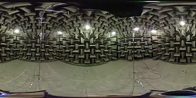
Anechoic chambers are commonly used in acoustics to conduct experiments in nominally "free field" conditions, free field meaning that there are no reflected signals. All sound energy will be traveling away from the source with almost none reflected back. Common anechoic chamber experiments include measuring the transfer function of a loudspeaker or the directivity of noise radiation from industrial machinery. In general, the interior of an anechoic chamber can be very quiet, with typical noise levels in the 10–20 dBA range. In 2005, the best anechoic chamber measured at −9.4 dBA. In 2015, an anechoic chamber on the campus of Microsoft broke the world record with a measurement of −20.6 dBA. The human ear can typically detect sounds above 0 dBA, so a human in such a chamber would perceive the surroundings as devoid of sound. Anecdotally, some people may not like such silence and can become disoriented.
The mechanism by which anechoic chambers minimize the reflection of sound waves impinging onto their walls is as follows: In the included figure, an incident sound wave I is about to impinge onto a wall of an anechoic chamber. This wall is composed of a series of wedges W with height H. After the impingement, the incident wave I is reflected as a series of waves R which in turn "bounce up-and-down" in the gap of air A (bounded by dotted lines) between the wedges W. Such bouncing may produce (at least temporarily) a standing wave pattern in A. During this process, the acoustic energy of the waves R gets dissipated via the air's molecular viscosity, in particular near the corner C. In addition, with the use of foam materials to fabricate the wedges, another dissipation mechanism happens during the wave/wall interactions. As a result, the component of the reflected waves R along the direction of I that escapes the gaps A (and goes back to the source of sound), denoted R', is notably reduced. Even though this explanation is two-dimensional, it is representative and applicable to the actual three-dimensional wedge structures used in anechoic chambers.
The absorptive wedges that line the room are typically sized so that their depth is approximately a quarter of the wavelength of the lowest frequency to be absorbed. This requirement sets the chamber's low-frequency cut-off, below which the lining no longer absorbs efficiently and the boundaries cease to behave anechoically; achieving a low cut-off therefore requires correspondingly deep wedges.
Semi-anechoic and hemi-anechoic chambers
Full anechoic chambers aim to absorb energy in all directions. To do this, all surfaces, including the floor, need to be covered in correctly shaped wedges. A mesh grille is usually installed above the floor to provide a surface to walk on and place equipment. This mesh floor is typically placed at the same floor level as the rest of the building, meaning the chamber itself extends below floor level. This mesh floor is damped and floating on absorbent buffers to isolate it from outside vibration or electromagnetic signals.
In contrast, semi-anechoic or hemi-anechoic chambers have a solid floor that acts as a work surface for supporting heavy items, such as cars, washing machines, or industrial machinery, which could not be supported by the mesh grille in a full anechoic chamber. Recording studios are often semi-anechoic.
The choice between a full anechoic chamber and a semi-anechoic chamber depends on the type of measurement. Sound power measurements according to ISO 3745 require a qualified free-field environment, which can be provided by either type, though the standard specifies different qualification procedures for each. Semi-anechoic chambers with a reflective floor are particularly suited for testing machinery and vehicles, as the floor simulates the ground plane present during normal operation. The related standard ISO 3744 describes sound power measurements using a reflecting plane, which is the typical configuration in a semi-anechoic facility.
The distinction between "semi-anechoic" and "hemi-anechoic" is unclear. In some uses they are synonyms, or only one term is used. Other uses distinguish one as having an ideally reflective floor (creating free-field conditions with a single reflective surface) and the other as simply having a flat untreated floor. Still other uses distinguish them by size and performance, with one being likely an existing room retrofitted with acoustic treatment, and the other a purpose-built room which is likely larger and has better anechoic performance.
Sign in to keep reading
One more chapter is free with a Lably account.
Radio-frequency anechoic chambers
The internal appearance of the radio frequency (RF) anechoic chamber is sometimes similar to that of an acoustic anechoic chamber; however, the interior surfaces of the RF anechoic chamber are covered with radiation absorbent material (RAM) instead of acoustically absorbent material. Uses for RF anechoic chambers include testing antennas and radars, and they are typically used to house the antennas for performing measurements of antenna radiation patterns and electromagnetic interference.
Performance expectations (gain, efficiency, pattern characteristics, etc.) constitute primary challenges in designing stand alone or embedded antennas. Designs are becoming ever more complex with a single device incorporating multiple technologies such as cellular, WiFi, Bluetooth, LTE, MIMO, RFID and GPS.
Radiation-absorbent material
RAM is designed and shaped to absorb incident RF radiation (also known as non-ionising radiation) as effectively as possible, from as many incident directions as possible. The more effective the RAM, the lower the resulting level of reflected RF radiation. Many measurements in electromagnetic compatibility (EMC) and antenna radiation patterns require that spurious signals arising from the test setup, including reflections, are negligible to avoid the risk of causing measurement errors and ambiguities.
Effectiveness over frequency
Waves of higher frequencies have shorter wavelengths and are higher in energy, while waves of lower frequencies have longer wavelengths and are lower in energy, according to the relationship where lambda represents wavelength, v is phase velocity of wave, and is frequency. To shield for a specific wavelength, the cone must be of appropriate size to absorb that wavelength. The performance quality of an RF anechoic chamber is determined by its lowest test frequency of operation, at which measured reflections from the internal surfaces will be the most significant compared to higher frequencies. Pyramidal RAM is at its most absorptive when the incident wave is at normal incidence to the internal chamber surface and the pyramid height is approximately equal to , where is the free space wavelength. Accordingly, increasing the pyramid height of the RAM for the same (square) base size improves the effectiveness of the chamber at low frequencies but results in increased cost and a reduced unobstructed working volume that is available inside a chamber of defined size.
Installation into a screened room
An RF anechoic chamber is usually built into a screened room, designed using the Faraday cage principle. This is because most of the RF tests that require an anechoic chamber to minimize reflections from the inner surfaces also require the properties of a screened room to attenuate unwanted signals penetrating inwards and causing interference to the equipment under test and prevent leakage from tests penetrating outside.
Chamber size and commissioning
At lower radiated frequencies, far-field measurement can require a large and expensive chamber. Sometimes, for example for radar cross-section measurements, it is possible to scale down the object under test and reduce the chamber size, provided that the wavelength of the test frequency is scaled down in direct proportion by testing at a higher frequency.
RF anechoic chambers are normally designed to meet the electrical requirements of one or more accredited standards. For example, the aircraft industry may test equipment for aircraft according to company specifications or military specifications such as MIL-STD 461E. Once built, acceptance tests are performed during commissioning to verify that the standard(s) are in fact met. Provided they are, a certificate will be issued to that effect. The chamber will need to be periodically retested.
Operational use
Test and supporting equipment configurations to be used within anechoic chambers must expose as few metallic (conductive) surfaces as possible, as these risk causing unwanted reflections. Often this is achieved by using non-conductive plastic or wooden structures for supporting the equipment under test. Where metallic surfaces are unavoidable, they may be covered with pieces of RAM after setting up to minimize such reflection as far as possible.
A careful assessment may be required as to whether the test equipment (as opposed to the equipment under test) should be placed inside or outside the chamber. Typically most of it is located in a separate screened room attached to the main test chamber, in order to shield it from both external interference and from the radiation within the chamber. Mains power and test signal cabling into the test chamber require high quality filtering.
Fiber optic cables are sometimes used for the signal cabling, as they are immune to ordinary RFI and also cause little reflection inside the chamber.
Health and safety risks associated with RF anechoic chamber
The following health and safety risks are associated with RF anechoic chambers:
- RF radiation hazard
- Fire hazard
- Trapped personnel
Personnel are not normally permitted inside the chamber during a measurement as this not only can cause unwanted reflections from the human body but may also be a radiation hazard to the personnel concerned if tests are being performed at high RF powers. Such risks are from RF or non-ionizing radiation and not from the higher energy ionizing radiation.
As the radiation-absorbent material (RAM) lining the chamber is highly absorptive of RF radiation, incident radiation will generate heat within the RAM. If this cannot be dissipated adequately there is a risk that hot spots may develop and the RAM temperature may rise to the point of combustion. This can be a risk if a transmitting antenna inadvertently gets too close to the RAM. Even for quite modest transmitting power levels, high gain antennas can concentrate the power sufficiently to cause high power flux near their apertures. Although recently manufactured RAM is normally treated with a fire retardant to reduce such risks, they are difficult to eliminate.